Genetic Optimization of Planetary Gearboxes Based on Analytical Gearing Equations
Future electric and hybrid electric vertical takeoff and landing vehicles will require high-efficiency and lightweight electric motor-driven propulsion systems. One key to designing an optimum electric motor-driven propulsion system, is to have a method for estimating the mass and efficiency of a gearbox for different power levels, motor speeds, and propeller speeds. Understanding the trade space for gearbox mass and efficiency allows the overall optimization of the propulsion system.
A number of past papers have detailed gearing theory, sizing, and efficiency calculations (Ref. 1). Past work at NASA has explored the optimum sizing of gearsets (Ref. 2). More recently, genetic optimization tools have been used to optimize gearboxes for terrestrial traction applications (Refs. 3–6). Genetic optimization algorithms are ideal for gearbox design due to the number of optimization variables that create discontinuities in the design space (Ref. 5). In this paper, a preliminary analytical gearbox optimization tool for electric vertical takeoff and landing vehicles is presented. Example gearbox sizing studies are carried out with the tool for electric multirotor type vehicles based on the NASA Revolutionary Vertical Lift Technology (RVLT) project 6-passenger quadrotor vehicle (Ref. 7).
The section “Gearbox Genetic Optimization” discusses the details of the optimization tool. Example tool results are presented in the section “Example Design Optimization Results” for multirotor-type vehicles based on the RVLT quadrotor concept vehicle. The “Conclusion” section outlines future tool improvement and development plans.
Gearbox Genetic Optimization Tool
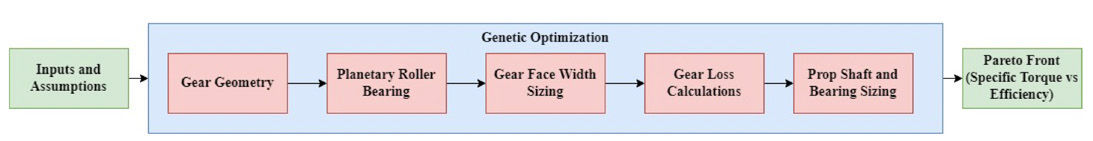
A flow diagram for the design tool is given in Figure 1. The following sections discuss each of the boxes in the flow diagram in order. The tool is presented in the context of a single or two-stage planetary gearbox.
Figure 1—Flow diagram for gearbox genetic optimization tool.
Input, Constants, and Assumptions
Table 1 provides the inputs and assumptions used in this paper. Along with basic output speed, power, and gear ratio, the tool requires a target life and reliability to size the gears and bearings. Gear, oil and other material information must be provided to estimate the life and power loss of the gearbox. Propeller loading information can optionally be provided for a given application. In this paper, the bulk of the propeller loading properties are based on the RVLT quad rotor concept vehicle. Hub moments in cruise are estimated based on the rotor disk loading, rotational speed, radius, and cruise velocity. These values are used as an example case. Ideally, actual values would be applied for a given target propeller design specification.
Target life
5000 h
Propellor thrust
0.006*Power
Target reliability
99.9 percent
Prop drag coefficient
0.015
Gear Material
Steel
Prop tip speed
167 m/s
Gear steel modulus
200 GPa
Prop hub moment
Estimated
Gear steel Poisson’s ratio
0.3
Vehicle cruise velocity
31.5 m/s
Gear steel hardness
627 HB
Propellor material
Carbon fiber
Gear steel fatigue bending strength
517 MPa
Oil viscosity
100 cSt
Gear steel fatigue contact strength
1.90 GPa
Air viscosity
0.02
Housing material
Aluminum
Shaft material
Steel
Gear pressure angle
20 degrees
Gear type
Spur gears
Table 1—Assumptions and inputs used in this paper.
The code uses 3 genetic optimization variables for single-stage planetaries and 7 variables for two-stage planetaries. For each stage, sun gear tooth count, ring gear diameter, and number of planets are used as optimization variables. The seventh variable for the two-stage planetary is the gear ratio of the first stage. Other parameters like gear tooth pressure angle, listed as an assumption in Table 1, can also be used as genetic optimization variables if desired.
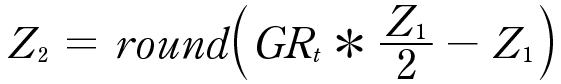
The 2D geometry of each gear set is generated based on the inputs provided to the fitness function by the genetic optimizer. For a single-stage planetary, first the ring and planet gear tooth counts are calculated based on the target gear ratio and the input sun gear tooth count.
(1)
(2)
where Z1 is the sun gear tooth count, Z2 is the planet gears tooth count and Z3 is the ring gear tooth count. Because Z2 must be rounded to an integer value number of gear teeth in Equation 1, actual gear ratio is calculated for the gear stage as,
(3)
The code verifies that the actual gear ratio, rounded to the nearest whole number, is equal to the target gear ratio. Input parameter sets that do not meet this target are discarded in genetic optimization.
The gear ratio of the planets relative to the sun gear is defined as
[advertisement]
(4)
The rotational speed of the sun gear is defined as
(5)
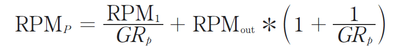
The rotational speed of the planets is defined as
(6)
Whether the planetary stage can be assembled is verified by checking if
(7)
is equal to a whole number (Ref. 1). Np is the number of planet gears. Input parameter sets that result in a planetary stage that is not possible to assemble are discarded in the genetic optimization.
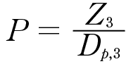
The diametral pitch of the planetary stage is calculated using the ring gear tooth count and input diameter.
(8)
where P is the gear pitch. The pitch radius of all the gears in the set is then calculated as
(9)
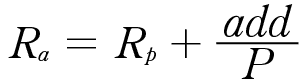
where Rp is the pitch radius. The tooth tip radius of the sun and planet gears is calculated as
(10)
where Ra is the tip radius and add is the gear addendum ratio. Ring gear tip radius is calculated as
(11)
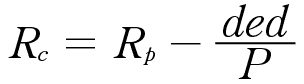
Gear tooth base radius for the sun and planet gears is calculated as
(12)
where Rc is the gear tooth base radius and ded is the gear dedendum ratio. Ring gear tooth base radius is calculated as
(13)
Gear base radii are calculated as
(14)
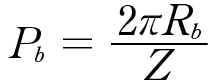
where Rb is the gear base circle radius and i is the gearset pressure angle. The base pitch of the gears is calculated as
(15)
Gear center distance between the sun and planet gears is calculated as
(16)
Gear center distance between the ring and planet gear is calculated as
(17)
The length of a sun-planet gear tooth contact along the line of action is calculated as
(18)
where X12 is the length of a sun-planet gear tooth contact (Ref. 1). The length of a planet-ring gear tooth contact along the line of action is calculated as
(19)
where X23 is the length of a planet-ring gear tooth contact (Ref. 1). Contact ratios are calculated as
(20)
where CR is the contact ratio of each mesh (planet-ring and sun planet). Contact ratios for both meshes are required to be between 1.2 and 2 in this paper (Ref. 1).
Gear tooth thickness calculations are carried out for the sun gear only. First an initial estimate of gear tooth thickness at the pitch circle is made as
(21)
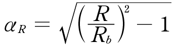
Tooth thicknesses at the gear tooth inner radius and outer radius are calculated by calculating the corresponding roll angle:
(22)
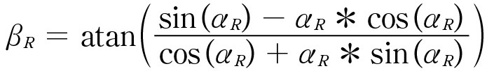
where αR is roll angle at radius R. The angular position of a gear tooth at a given radius is defined as
(23)
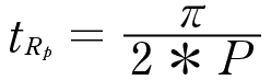
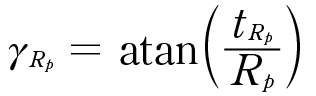
where βR is the angular position of the face of the gear tooth at radius R. The span angle of the gear tooth at the pitch radius Rp is calculated as
(24)
where γRp is the span angle of the gear tooth at radius Rp. The tooth span angle at any other radius, R, can then be calculated as
(25)
Gear tooth thickness at any radius R, can then be calculated as
(26)
The radius of the fillet at the base of the gear tooth, hobR, is calculated from the difference between the available space at the tooth base and the size of the tooth at the base. A max size for hobR is set to the 0.25/P. A min size is set to 0.25 mm.
Gear tooth thickness at the pitch radius size is iteratively decreased until at least 0.2 mm of clearance exists between the gear teeth in mesh. If the tooth thickness at the pitch radius drops below 3 mm, the gear design is discarded in the genetic optimization. 3 mm is used as a rough estimate of the limits of manufacturing size for a planetary gearset of appropriate size for eVTOL applications.
The radius of the center of the gear tooth base fillet is calculated as
(27)
where Rf is the radius of the center of the gear tooth. The tooth thicknesses for bending stress calculations tRf and t0 are calculated at this radius.
Planetary Bearing Calculation
In the tool it is assumed that spherical roller bearings are used to transmit torque from the planet gears to the planet carrier due to their high load capacity and ability to react moments and axial forces. The force on each roller bearing is estimated as
(28)
where x is the output torque of the planetary stage. The bearing life equations from (Ref. 8) are used to evaluate all the bearings in a spherical roller bearing database composed from (Ref. 9). Max speed limitations for each bearing are also checked relative to the planet gear rotational speed. The lowest mass bearing that is able to meet the target life, speed requirements, and fit dimensionally within the planet gear is selected. If no bearing meets the requirements, the input parameter set is discarded in the genetic optimization.
Roller bearing losses are calculated using the equations found in Ref. 10 and are included in the efficiency estimate for the planetary stage.
Gear Face Width Sizing
The face width of a given gear tooth set is calculated by first calculating the min required tooth width for bending stress, contact stress, and pitting life respectively. Gear tooth width for all the gears in the planetary gear train is set to the maximum of the three calculated minimum required thicknesses. Gear mass and losses are calculated using that face width. The following sections describe each of the gear tooth face width calculations.
Gear Tooth Bending Stress
The max allowable bending stress in a gear tooth is defined as
(29)
where Sb,max is the max allowable bending stress, St,fatigue is the fatigue strength of the steel, kL is the life factor, SFt is the bending fatigue safety factor, kt is the temperature factor, and kr is the reliability factor (Ref. 1). Assuming an AGMA grade 3 case carburized gear tooth, St,fatigue is estimated as 517 MPa (Ref. 11). SFt is set to 1.25 in this paper. kt is taken to be unity, assuming the gear oil temperature is in the range of 60–80 °C, and correspondingly, the gear tooth temperature is less than 177 °C (Ref. 1). kr in this paper is taken to be 1.5 for 99.99 percent reliability (Ref. 1). kL is defined based on Figure 18 in (Ref. 11) as
(30)
where N is the number of stress cycles the gear tooth experiences.
The bending stress is calculated on the pinion for each gear set. The method described on page 33 of Ref. 1 is used. The calculation is carried out at the highest point of single tooth contact. To define the highest point of single tooth contact, first the corresponding roll angle is calculated as defined in Ref. 2
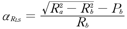
(31)
The pressure angle at RHS is calculated as
(32)
RHS is calculated as
(33)
Tooth thickness at RHS, tRHS, is calculated using Equations 21–26.
An iterative solver is then used to define the angle, δ, which defines the location on the gear tooth fillet for gear stress calculations (Ref. 1). An initial guess of r/4 is used for δ0. A next approximation of d is then estimated as
(34)
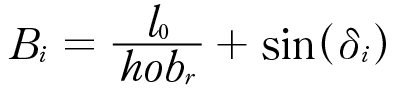
where Bi is defined as
(35)
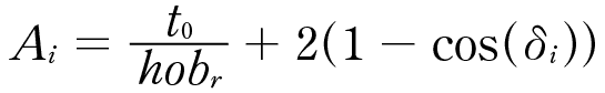
and Ai is defined as
(36)
where
t0 is the distance between centers of the gear tooth fillets
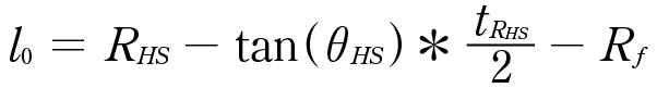
(37)
l0 is the distance from the radius of intersection of the line of action with the center of the gear tooth and the radius of the center of the fillet Rf,
(38)
Three iterations of the iterative solver are used to refine the angle δ. The required face width of the gear to keep bending stress below Sb,max is then calculated as
(39)
where
Fb is the estimated minimum required face width of the gear set needed to keep bending stress below the max allowable
WN is the force applied at the highest point of single tooth contact.
ts is the thickness of the gear tooth at the location gear stress is calculated
(40)
l's is the distance from the radius of intersection of the line of action with the center of the gear tooth to the radius of the point of max stress
(41)
ls is the radial distance from the highest point of single tooth contact to the radius of the point of max stress
(42)
v is Poisson’s ratio for the gear steel.
Gear Tooth Contact Stress Calculations
The max allowable contact stress in a gear set is defined as
(43)
where Sc,max is the max allowable contact stress, Sc,fatigue is the contact fatigue strength of the steel, kL is the life factor, SFt,c is the contact fatigue safety factor, kt is the temperature factor, and kr is the reliability factor (Ref. 1). Assuming an AGMA grade 3 case carburized gear tooth, Sc,fatigue is estimated as 1,896 MPa (Ref. 11). SFc is set to 1.25 in this paper. kt and kr are the same as those used for bending stress calculations. kL is defined based on Figure 17 in Reference 11 as
(44)
where N is the number of stress cycles the gear tooth experiences.
Gear tooth contact stress and life calculations are carried out at the lowest point of single tooth contact on the gear set’s pinion. The roll angle of the lowest point of single tooth contact is calculated as
(45)
Pressure angle at the point of lowest single tooth contact is calculated as
(46)
The required face width needed to maintain contact stress below Sc,max is calculated as
(47)
where E is the elastic modules of the material (Ref. 2).
Gear Tooth Pitting Life Calculation
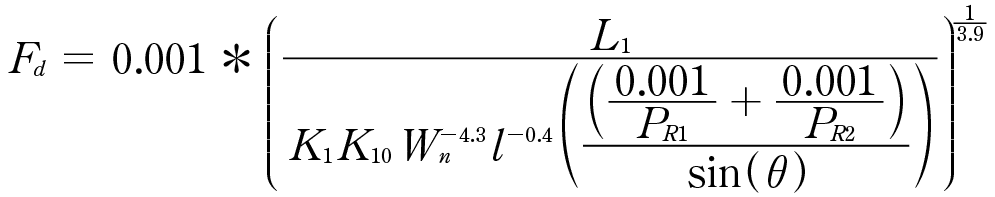
A third required face width calculation is also used based on the method described in Section 5.2 of Ref. 1.
(48)
where
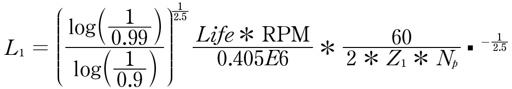
L1 is a constant defined
(49)
K1 is set to 1.6, assuming the gears are shot peened AISI 9310 per Table 7 of Ref. 1
K10 is a constant equal to 6.44E9 per Ref. 1
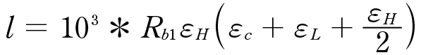
l is the length of the contact
l is calculated as
(50)
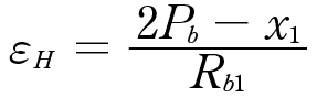
where
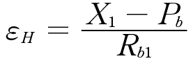
εH is the pinion roll angle increment for single tooth contact, Ref. 1
(51)
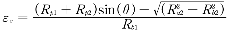
εc is the pinion roll angle from the base of the involute to the start of double tooth contact Ref. 1
(52)
εL is the pinion roll angle increment for double tooth contact, Ref. 1
(53)
Gear Face Width and Mass
Gear face width, F, is defined as the max of Fb, Fc, and Fd. If the largest of these face width values is less than 5 mm, face width is set to 5 mm. 5 mm is selected as the minimum allowable face width so that the gear maintains out-of-plane stiffness and has reasonable face area to account for misalignment and 3D gear tooth features like tooth crowning.
The mass of an external gear is estimated as
(54)
where Rimt is an input estimate of the required gear rim thickness to avoid distortion of the gears and Dsteel is the density of the steel used to make the drivetrain. 5 mm is used in this paper so that the gear rims have reasonable stiffness and can support centripetal loads. Integrating a more detailed and physics-based gear rim design is the target of future work.
The mass of an internal gear is defined as
(55)
For a planetary gear member, the mass of the roller bearings and an estimate of the carrier mass are included. Roller bearing mass is taken to be 66 percent of the mass listed in Ref. 9, assuming some portion of the inner and outer races of the bearings is integrated into the rim of the gear and the gear’s shaft. An estimate of planet carrier mass is also included
(56)
This planet carrier mass estimate only serves as a rough mass estimate that scales with the size of the gear set and number of planets. Adding a higher fidelity methodology for carrier mass estimate is a potential area of improvement for the code.
Gear Efficiency Calculations
With the gearset face width defined, windage, sliding, and rolling loss for each gear mesh are calculated using the method described in Ref. 12.
Windage Loss Calculation
For the sun gear windage power loss is calculated as
(57)
where Pw1 is the windage loss of the pinion gear and n is the viscosity of the oil.
The windage power loss of the planet gears is estimated as
(58)
Sliding Loss
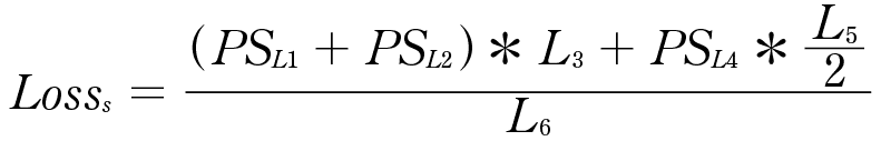
Sliding loss is defined as
(59)
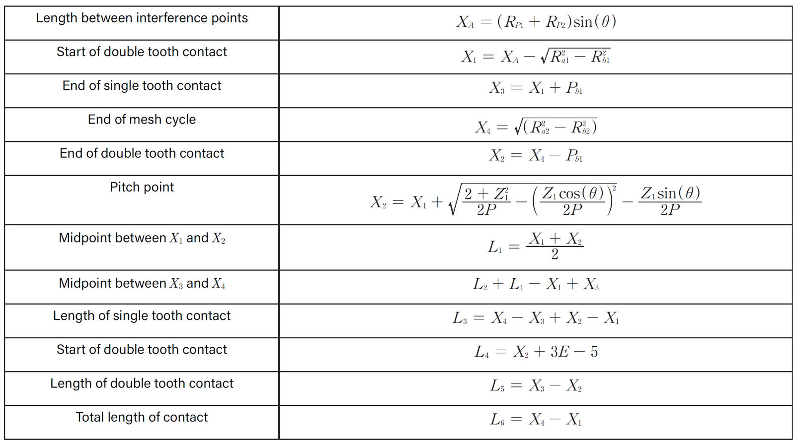
where PSL is the instantaneous sliding loss along the length L of the gear tooth contact. The lengths L are defined below in Table 2 for a pair of external gears and Table 3 for an external gear mating with an internal gear.
Table 2—Mesh lengths and positions for two external gears meshing.Table 3—Mesh lengths and positions for an external and an internal gear meshing.
(60)
fL is the friction coefficient defined as
(61)
VSL is the average sliding velocity over length L
(62)
VTL is the average rolling velocity over length L
(63)
The friction coefficient, fL, from Equation 61 is based on a curve fit to an experimental data set (Ref. 1).
The use of a logarithmic function as a fitting function leads to the fL calculated by the equation at high surface velocities going negative. To avoid these negative predicted values, a min value for fL is set to 0.01 in this paper per the recommendations of Ref. 1.
Rolling Loss
Gear tooth rolling loss is calculated as
(64)
where PRL is the instantaneous power loss along the length L of the gear tooth contact
(65)
where hL is the hydraulic film thickness at point L
(66)
where ReqL is the equivalent contact radius
(67)
The equivalent radius of the gear, RogL, is defined as
(68)
for an internal gear and as
(69)
for an external gear.
The equivalent radius of the pinion, RopL, is
(70)
Total Losses
For a planetary gear set, total loss is calculated as the sum of the windage losses as well as the rolling and sliding losses from each gear tooth mesh.
(71)
Shaft and Bearing Mass Estimate Calculations
In the code, it is assumed that the gearbox is responsible for handling the vehicle's propeller loads. Vehicle hub moments, propeller lift and drag force, and the mass and moment of inertia of the propeller assembly are required inputs. Peak vehicle accelerations and pitch/roll/yaw rates are also required. The assumed layout of bearings in the drivetrain of a single planetary gearbox is shown in Figure 2. Note that the input to the sun gear shaft and how it is integrated with the gearbox is neglected for all gearboxes in this paper unless it is another gearing stage.
An iterative solver is used to create a rough bearing and shaft mass estimate. A bearing data set composed of super precision angular contact ball bearings based on Reference 13 is used as a reference bearing data set in the design tool. From the database, for each run, all bearings that do not fit within the ID of the smallest sun gear are eliminated from consideration. Shaft length, see Figure 2, is initially set to 2 m and then iterated down in 0.25 m increments until a minimum mass bearing and shaft set is found. At each shaft length, loads are calculated at both the aft and forward bearing positions using the balance of forces and moments and assuming the shaft behaves as a rigid body. All the bearings in the bearing database are evaluated for their ability to provide the target life at both the forward and aft bearing locations. For simplicity, it is assumed that the same bearing is used for the forward, aft, and all gear bearings that sit on the propeller shaft. Using the same bearing in all locations and only angular contact bearings for a propeller shaft likely is not optimum, but for a preliminary mass estimate, assuming that all the bearings are the same is a reasonable approximation.
Load case
Max
Nominal
Gx
2
0.1
Gy
0.2
0.1
Gz
2
1.1
Pitch rate
0.5
0.05
Roll rate
0.25
0
Percent of life
0.05
0.95
Table 4—Nominal and max load case used for propeller shaft and bearing sizing.
Figure 2—Assumed layout of gears and bearings for bearing load calculations.
Each bearing is evaluated for whether it can meet the target life with 99 percent reliability at the forward and aft bearing locations per the bearing lifing method described in Reference 8. Two different load cases are included per Table 4. For the forward bearing, if for a given bearing in the database, a single bearing is not sufficient, an iterative solver is used to find the number of bearings of that type needed in parallel to achieve the target bearing life. The number of bearings used is limited to 4. A knock down on the bearings' dynamic load carrying capacity of 20 percent is applied if more than one bearing is used. Bearings for which no solution is found to meet the target life are eliminated from consideration.
A shaft is sized for each bearing set that meets the target life and reliability. The outer diameter (OD) of the shaft is set to the inner diameter (ID) of the bearing and an iterative solution method is used to size the ID of the shaft. At each shaft internal diameter, Bernoulli beam bending equations and shaft tensile and shear equations are combined to calculate the Von Mises stress in the shaft at the location of the forward bearing. Stress is required to be below the fatigue limit of the selected shaft material. In this paper, a limit of 300 MPa is used. Shafts that are not able meet the target stress requirement with even a solid shaft, are eliminated from consideration.
A total mass estimate for the shaft, aft bearing, forward bearing, and a housing is created for each shaft/bearing set that meets the requirements. Housing mass is estimated as
(72)
After iterating to solve for shaft length, the shaft/bearing set with the lowest mass is selected. Loss analysis is carried out for that bearing set per the method described in Reference 10 and included in the total drive efficiency estimate.
Example Design Optimization Results
Six studies were completed for the multirotor-type vehicles main propulsion gearboxes. Table 5 summarizes the studies. The first three studies target the effects of gearbox input and output speed explicitly for the RVLT 6 passenger all-electric concept vehicle. The other three studies target power scaling effects at constant output speed and relevant gear ratios for electric motors.
Study no.
Propellor speed, RPM
Power, kW
Gear ratio
1
400
140
3,5,8,10,15,20,30
2
550
140
3,5,8,10,15,20,30
3
700
140
3,5,8,10,15,20,30
4
400
50:50:500
10
5
400
50:50:500
20
6
400
50:50:500
30
Table 5—Details of six studies completed for this study.
For the studies, the estimated propeller properties change with rotational speed power. Table 6 lists a few relevant example cases for propeller properties. It should be noted that these are just estimates based on extrapolating data from the RVLT concept vehicles. In an ideal scenario, the propeller loading would be taken from a higher fidelity analysis.
Power, kW
Speed, RPM
Prop weight, kg
Prop radius, m
Prop drag, N
Prop thrust, N
Aero hub moment, Nm
140
700
177
2.28
121
8,232
849
140
550
177
2.9
196
8,232
1,059
140
400
177
3.99
371.6
8,232
1,466
50
400
63
3.99
371.6
2,940
524
300
400
379
3.99
371.6
17,640
3,141
450
400
569
3.99
371.6
26,460
4,712
Table 6—Estimated propeller loads for example cases.
Results for the first three studies (rotor and motor rotational speed sweeps) are given in Figure 3 to Figure 5.
Figure 3—Results of Study 1—Gear ratio sweep at 140 kW and 400 RPM propeller speed. Specific torque vs. efficiency.
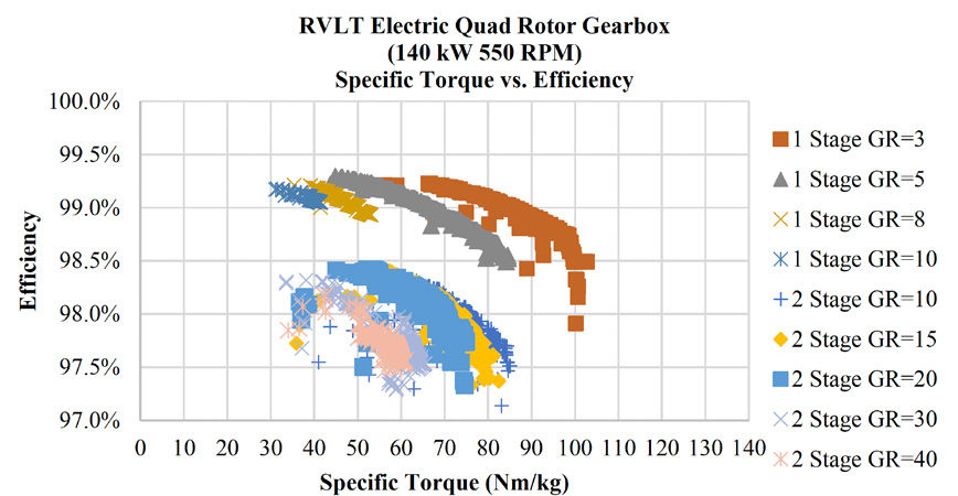
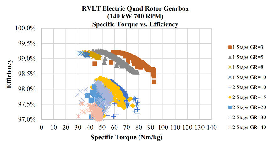
Figure 4—Results of Study 2—Gear ratio sweep at 140 kW and 550 RPM propeller speed. Specific torque vs. efficiency.Figure 5—Results of Study 3—Gear ratio sweep at 140 kW and 700 RPM propeller speed. Specific torque vs. efficiency.
In Figures 3–5, a clear trend of specific torque decreasing with increased gear ratio (increased motor speed) can be seen. Efficiency does not exhibit a significant trend with gear ratio, except for the difference between single and two-stage gearboxes. A drop off in efficiency occurs at gear ratio values around 40 for the 700 RPM case due to the very high RPM of the sun gear (28,000 RPM) in this case, as well as the relatively high overall ratio. Between the three plots at a given gear ratio, a reduction in gear-specific torque with increased propeller speed can be seen. This reduction corresponds to gearbox-specific torque decreasing with decreased torque, because despite the reduction in gear mass, the weight of the housing, shafts, and bearings does not reduce as significantly with reduced torque. This trend is illustrated more clearly for the results below from studies 4 to 6 with constant rotor speed and increasing power.
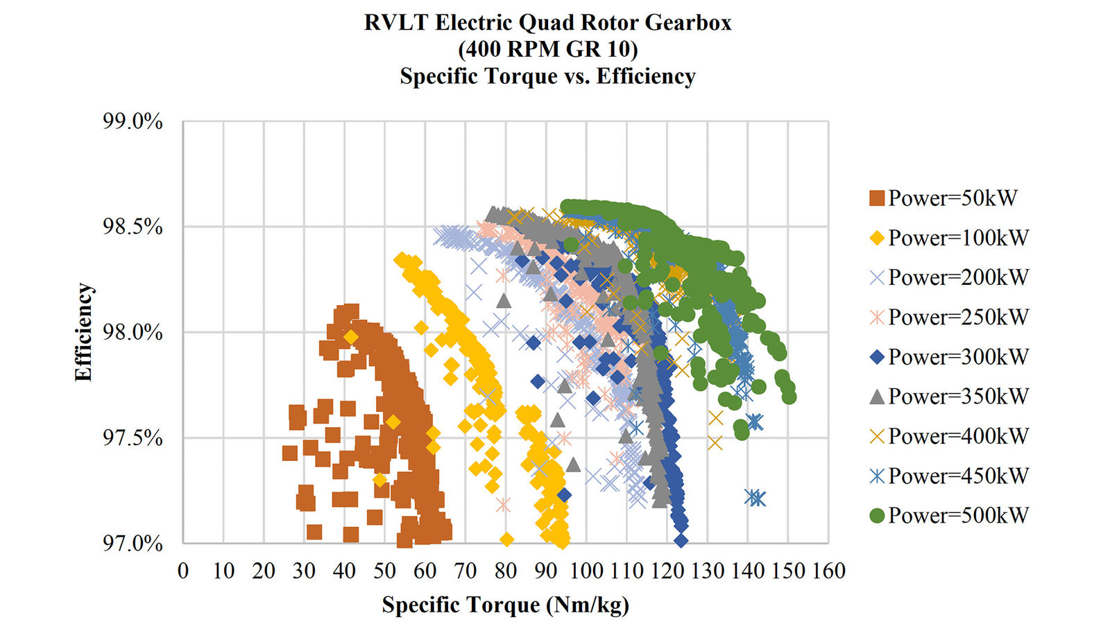
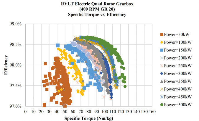
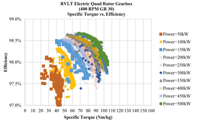
Figures 6–8 show the results of Studies 4–6 per Table 5. All of the results in these three studies were for two-stage planetary gearboxes. Gear ratios of 10, 20 and 30 were used, targeting a range of motor rotation speed from 4,000 to 12,000 RPM.
Figure 6—Results of Study 4—Power sweep at GR 10 and 400 RPM propeller speed. Specific torque vs. efficiency.Figure 7—Results of Study 5—Power sweep at GR 20 and 400 RPM propeller speed. Specific torque vs. efficiency.Figure 8—Results of Study 6—Power sweep at GR 30 and 400 RPM propeller speed. Specific torque vs. efficiency.
Figures 6–8 show clear trends for increasing gearbox-specific torque and efficiency with increased power/torque. As with Studies 1–3, comparing across plots, specific torque and efficiency are shown to drop with increased gear ratio.
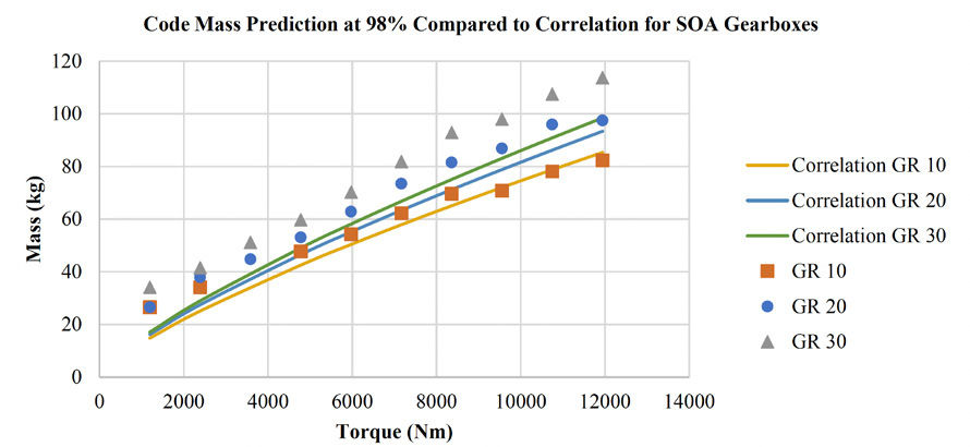
Figure 9—Comparison of code results for Studies 4–6 at 98 percent efficiency to the curve fit to real gearbox data from Reference 14.
Figure 9 shows the trend of torque versus mass at a constant 98 percent efficiency from studies 4 to 6. Along with the data from the studies, the trendlines from Reference 14 for state-of-the-art gearbox mass versus torque, gear ratio, and output speed are shown. The trendlines are based on curve fits to actual aerospace gearboxes. The curve fit defines mass in pounds as
(73)
where HP is the power of the gearbox in horsepower.
In Figure 9, the masses predicted by the code presented in this report and the trendline from Reference 14 have reasonable agreement, suggesting that the code provides good estimates of gearbox mass. The greater mass predicted by the code is likely driven by the relatively low fidelity design of the housing in the code. The discrepancy growing with higher gear ratio likely results from using constant efficiency data from the code. It is unlikely that one would not trade some efficiency for lower mass in the design of an actual aerospace gearbox.
Conclusions
This paper presents a preliminary version of a gearbox genetic optimization tool. The goal of the developed tool is to enable preliminary sizing of gearboxes for concept electric aircraft applications so that coupled optimization of electric motor-driven propulsion systems can be completed. Further development of the tool will look to add more capability to address different gear stage types and increase the fidelity of the gearbox design. The addition of a way to predict coolant requirements is also a needed improvement to enable optimization of electric aircraft drivetrain thermal management systems. At the cost of processing and solution speed, the analytical methodology presented here could be replaced with greater fidelity finite element models. Based on matching past correlations for gearbox mass, the method detailed in the paper appears to be reasonable for the preliminary design of electric motor drivetrains.
References
J.J. Coy, D. Townsend and E.V. Zaretsky, “Gearing,” NASA, Cleveland, 1985.
M. Savage, J.J. Coy and D.P. Townsend, “The Optimal Design of Standard Gearsets,” in Advanced Power Transmission Technology, 1983.
K. Deb and S. Jain, “Multi-Speed Gearbox Design Using Multi-Objective Evolutionary Algorithms,” Journal of Mechanical Design, vol. 125, no. 3, pp. 609–619, 2003.
M. Hofstetter, D. Lechleitner, M. Hirz, M. Gintzal and A. Schmidhofer, “Multi-objective gearbox design optimization for xEV-axle drives under consideration of package restrictions,” Forschung im Ingenieurwesen, vol. 82, pp. 361–370, 2018.
D. Schweigert, ME. Gerlach, A. Hoffmann, B. Morhard, A. Tripps, T. Lohner, M. Otto, B. Ponick and K. Stahl, “Multi-Speed Gearbox Design Using Multi-Objective Evolutionary Algorithms,” Vehicles, vol. 2, pp. 365–397, 2020.
D. Schweigert, M. Gerlach, A. Hoffmann, B. Morhard, A. Tripps, T. Lohner, M. Otto, B. Ponick and K. Stahl, “On the Impact of Maximum Speed on the Power Density of Electromechanical Powertrains,” Vehicles, vol. 2, pp. 365–397, 2020.
C. Silva, W. Johnson, K. Antcliff and P.D. Michael, “VTOL Urban Air Mobility Concept Vehicles for Technology Development,” in AIAA Aviation, Alanta, 2018.
SKF Group, “SKF Rolling Bearing Catalog," October 2018. [Online]. Available: https://www.skf.com/binary/77-121486/SKF-rolling-bearings-catalogue. pdf [Accessed January 2020].
SKF Group, “SKF model for calculating the frictional moment,” [Online]. Available: https://www.skf.com/binary/12-299767/0901d1968065e9e7-The- SKF-model-for-calculating-thefrictional-movement_tcm_12-299767.pdf [Accessed January 2020].
AGMA, “Fundamental Rating Factors and Calculation Methods for Involute Spur and Helical Gear Teeth,” American Gear Manufacturing Association, Alexandria, 2001.
N.E. Anderson and S.H. Loewenthal, “Spur-Gear-System Efficiency at Part and Full Load,” NASA, Cleveland, 1980.
SKF Group, “SKF Super Precision Bearing Catalog,” March 2016. [Online]. Available: https://www.skf.com/binaries/pub12/Images/0901d19680495562-Super-precisionbearingscatalogue--- 13383_2-EN_tcm_12-129877.pdf [Accessed July 2020].
G.V. Brown, A.F. Kascak, B. Ebihara, D. Johnson, B. Choi, M. Siebert and C. Buccieri, “NASA Glenn Research Center Program in High Power Density Motors for Aeropropulsion,” NASA, Cleveland, 2005.
R. Errichello, “A Rational Procedure for Designing Minimum-Weight Gears,” Gear Technology, pp. 10–14, November/December 1991.
Originally published by NASA as NASA/TM-20220008843
[advertisement]
×
Like What You see?
Power Transmission Engineering is THE magazine of mechanical components. PTE is written for engineers and maintenance pros who specify, purchase and use gears, gear drives, bearings, motors, couplings, clutches, lubrication, seals and all other types of mechanical power transmission and motion control components.
*Unsubscribe any time. Full details in our privacy policy


 Power Transmission Engineering is THE magazine of mechanical components. PTE is written for engineers and maintenance pros who specify, purchase and use gears, gear drives, bearings, motors, couplings, clutches, lubrication, seals and all other types of mechanical power transmission and motion control components.