[advertisement]
Feature Articles

October 7, 2026


Feature Articles

The Right Linear Drive Starts With the Right Questions

Thomson Industries deconstructs drive technology selection

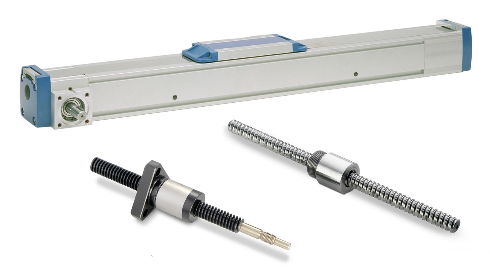
Figure 1—Specifying a predetermined linear drive such as a lead or ball screw or belt-driven unit without first understanding the application’s operating requirements can lead to significant wastes in time, effort and expense. All images: (Regal Rexnord)

Engineers rarely approach a linear motion project without some idea of the drive technology they expect to use. Previous experience may suggest a ball screw for an application requiring high precision, a lead screw where simplicity and low maintenance are priorities, or a belt-driven system for a long, high-speed axis. Motion designers therefore often begin discussions with manufacturers by requesting a particular solution. The questions that follow, however, are largely the same regardless of the technology specified. Instead of confirming the requested product, the focus tends to be more on understanding what the machine is expected to accomplish.

Load, operating speed and required stroke provide an initial picture of the application but not a complete one. Duty cycle, positioning accuracy, mounting orientation and the operating environment can all influence the final drive technology choice, while complete information about force direction and applied moments is essential if the system is to be sized correctly. A payload figure on its own does not explain how a linear unit will be loaded. The position and center of gravity of the load, together with the forces generated during acceleration and deceleration, can introduce lateral loads or overturning moments that materially affect system capacity and expected service life. Until those requirements are defined, even a technically plausible recommendation is based on an incomplete understanding of the machine.

Specifying a predetermined drive technology can also prevent designers from considering alternatives that may be better suited to the overall operating requirements. A lead screw often appears to be the logical choice for a simple, cost-effective axis, but the required speed or duty cycle could move the application beyond its practical operating range. A ball screw may provide the necessary load capacity and positioning accuracy yet become unsuitable where a long stroke and high rotational speed introduce critical speed limitations. Conversely, a belt-driven system may easily accommodate the required travel and velocity but offer either more positioning capability than the application needs or insufficient accuracy for the task. Successful drive technology selection therefore begins by eliminating those that cannot satisfy the application’s operating requirements, rather than comparing ball screws, lead screws and belt drives as though they were interchangeable solutions. The drive technology is the outcome of the engineering process, not its starting point (Figure 1).

Defining the Application

Considering alternatives to the preferred drive technology allows the discussion to focus on the operating requirements that ultimately determine whether that technology is appropriate. In most cases, five parameters quickly narrow the field: load, speed, stroke, duty cycle and positioning accuracy. None should be considered in isolation. A change to one can influence the importance of another, which is why experienced application engineers consider them together rather than as a checklist.

Load, for example, involves considerably more than just the weight being moved. The linear unit must be sized for the forces it will experience, including their direction and any moments applied to the carriage. The mounting arrangement, center of gravity and dynamic forces generated during acceleration can all influence the final calculation. Two machines carrying the same payload may therefore place very different demands on the drive system. Understanding how those forces are transmitted through the mechanism is essential if the calculated service life is to reflect real operating conditions rather than theoretical loading.

Share and save:


This article appeared in the October 2026 issue.


Read PDF

[advertisement]

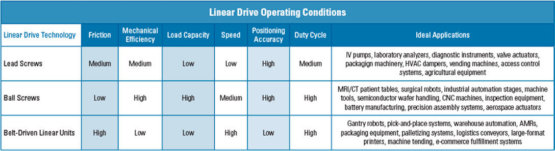
Speed and stroke begin to define the practical limits of each drive technology. A screw-driven system operating over a relatively short travel may perform exceptionally well but increasing the stroke while maintaining the same operating speed can introduce critical speed limitations as the screw length increases. At that point, a belt-driven solution may become the more practical option, not because it is inherently better, but because it is better suited to the application's combination of travel and velocity. Looking at these requirements together allows unsuitable technologies to be eliminated early, simplifying the drive technology selection process before detailed sizing begins (Figure 2).

Operating pattern is equally important. An axis that indexes only a few times each hour places very different demands on a drive system than one operating continuously throughout every production shift—even when load and travel remain the same. Likewise, specifying positioning accuracy beyond what the machine requires may increase cost without improving performance, while underestimating that requirement can compromise the finished design. The objective is to match the capabilities of the drive system to the machine's actual requirements, rather than specifying for performance the application does not need.

Matching the Drive Technology to the Application

Once the operating requirements are understood, the range of suitable drive technologies has usually narrowed considerably. Rather than comparing every available option, determine which solution offers the best balance of performance, service life and cost for the operating requirements that have been established. Although there is often some overlap between technologies, each has characteristics that naturally suit particular types of applications.

Long-stroke, high-speed applications are a good example. Engineers from a motion control solutions manufacturer recently worked with a customer developing a camera system that needed to travel more than 20 feet at several meters per second. Those requirements immediately changed the drive technology selection process. A screw-driven system of that length would be constrained by critical speed limitations as rotational speed increased, making it more difficult to achieve the required performance. A belt-driven actuator, however, could accommodate both the travel distance and operating speed while maintaining the motion profile the application demanded. Similar considerations apply to gantries, transfer systems and other applications where long travel and high velocity are more important than achieving the highest possible positioning accuracy.

Lead screws suit a different range of operating conditions. Because the nut slides along the screw rather than rolling on recirculating ball bearings, lead screws operate with greater friction and lower mechanical efficiency than a ball screw. This characteristic limits their suitability for higher loads and continuous, high-speed operation, but it can also offer advantages where those demands do not exist. Compact medical equipment, laboratory instruments and desktop automation systems often place greater value on quiet operation, simple construction and reduced maintenance than maximum speed or load capacity. Polymer lead screw nuts can also operate with minimal lubrication, while certain screw and lead combinations can provide self-locking characteristics that help resist backdriving in vertical applications.

Where higher loads, greater positioning accuracy and demanding duty cycles are combined, ball screws frequently become the preferred solution. Their rolling contact delivers high mechanical efficiency, reducing friction and the torque required from the motor while supporting heavier loads and repeatable positioning performance over long operating lives. A vertical manufacturing axis, for example, may require the combination of high load capacity, speed and precision that naturally favors a ball screw. That high efficiency also makes ball screws susceptible to backdriving, however, so vertical applications will typically require an appropriate braking solution to hold the load if power is removed. The final specification is therefore driven by the complete operating requirement rather than the characteristics of the screw alone.

Figure 2—When the operating requirements of an application are considered up front, the linear drive selection process can be greatly simplified. This table details the operating conditions of three popular linear drive technologies: lead screws, ball screws and belt-driven linear units.

Looking Beyond Basic Performance Specifications

Once the primary motion requirements have narrowed the range of suitable drive technologies, engineers can evaluate the remaining options against a broader set of application considerations. Service life, efficiency, maintenance requirements and environmental conditions may not determine the initial technology choice on their own, but they can become decisive when several solutions satisfy the basic load, speed, stroke, duty cycle and positioning requirements. These factors should therefore be considered as part of the same application-led selection process rather than as isolated specifications.

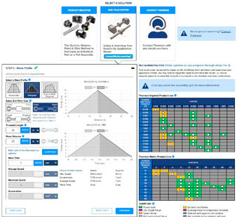
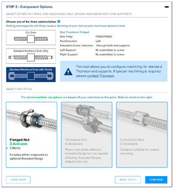
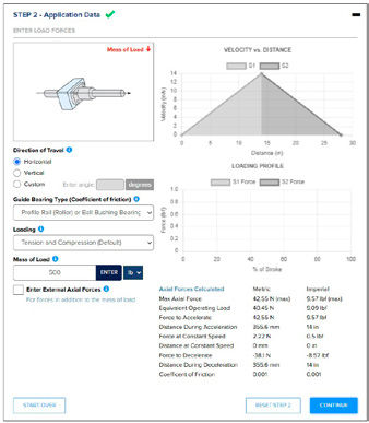
Figure 3—Sizing and selection software such as Thomson Industries’ Linear Motioneering online tool helps engineers determine the optimal drive system using key application parameters.

One of the most common misconceptions is that remaining within a published load rating automatically means a system has been sized correctly. In reality, the load rating simply indicates that the product is capable of carrying that load. Service life decreases as loading increases, so two separate systems may both satisfy the basic load requirement while offering very different operating lives. An application engineer may therefore recommend moving to a larger screw or actuator even though the original selection remains within its published capacity. The larger system may require more installation space and increase initial cost, but it can also provide the service life the machine requires. Equally, where a shorter design life is acceptable or installation space is restricted, a smaller solution may still represent the most appropriate engineering decision. The objective is to achieve the required service life while balancing performance, package size and overall machine requirements.

Environmental conditions can have an equally significant influence on the final specification. Exposure to moisture, washdown procedures, abrasive contamination or corrosive chemicals may require anodized components, stainless steel hardware, plated screws or enhanced sealing arrangements. These considerations should be identified as part of the original application review rather than addressed after the drive has been selected. A system that performs exceptionally well in a clean manufacturing environment may require a very different specification when installed in food processing, outdoor equipment or other demanding operating conditions. Considering these factors from the outset helps ensure the selected system will perform reliably throughout its intended operating life.

Using Software to Support Selection

Modern sizing software has become an important part of the selection process because it allows engineers to evaluate application data against a wide range of products quickly and consistently. Entering parameters such as load, stroke, travel speed, force direction and applied moments enables the software to eliminate unsuitable options, compare expected service life and identify technically viable solutions far more efficiently than manual calculations alone (Figure 3).

[advertisement]

The software, however, is only as effective as the information entered, and it cannot make the engineering decisions on the designer's behalf. Experienced application engineers are still needed to interpret the results, understand the trade-offs between performance, service life, package size and cost, and recognize when a technically acceptable solution may not be the most appropriate one for the machine. The software accelerates and simplifies the selection process; engineering judgment ensures the right decision is made.

The Application Remains the Starting Point

Successful linear drive selection begins with understanding the application rather than choosing a preferred technology. Once the operating requirements have been properly defined, the most suitable solution usually becomes clear as the alternatives that cannot meet the application’s demands have already been eliminated.

thomsonlinear.com


×

Like What You see?

Power Transmission Engineering magazinePower Transmission Engineering is THE magazine of mechanical components. PTE is written for engineers and maintenance pros who specify, purchase and use gears, gear drives, bearings, motors, couplings, clutches, lubrication, seals and all other types of mechanical power transmission and motion control components.

E-mail

Choose at least one from the options below:

 Power Transmission Engineering magazine, published 8 times per year (print or digital).

 Power Transmission Engineering e-mail newsletter, published weekly.

 Special Offers and promotions via e-mail from Power Transmission Engineering's advertisers and partners.

*Unsubscribe any time.
Full details in our privacy policy
Already a subscriber? Log in