


Measuring Pitch Diameter
Robert E. Smith
Wait a minute, we don’t measure pitch diameter. We’re sometimes asked to measure it by customers, though, especially ones with older drawings or with gear orders outsourced by them. But measuring pitch diameter is a fallacy.
When a gear inspector takes a gage and uses its anvils or pins on diametrically opposed tooth spaces, what he’s actually measuring is changes in tooth thickness.
Pitch diameter is the diameter of a pitch circle. The standard (reference) pitch circle is defined as: "The circle which intersects the involute at the point where the pressure angle is equal to the profile angle of the basic rack." The standard pitch diameter, D, is the diameter of this standard (reference) pitch circle and is obtained by D = N/Pd or--in the metric system--by D = Nm, where N is the number of teeth, Pd is the standard transverse diametral pitch, and m is the module. See the American Gear Manufacturers Association standard ANSI/AGMA 1012-F90, Gear Nomenclature Terms, Definitions, Symbols, and Abbreviations.
Therefore, the standard pitch diameter is actually a reference dimension that doesn’t change as long as the number of teeth and the diametral pitch or module don’t change. The standard pitch diameter shouldn’t have a tolerance and isn’t measured.
When manufacturing a gear, the cutting or grinding tool may be fed in or out to make a size change. What this actually does is make the teeth thicker or thinner, at the standard pitch circle (gear reference circle). The standard pitch diameter, however, doesn’t change. See Figure 1, which appears as Figure B.1 in AGMA 913-A98, Method for Specifying the Measuring Geometry of Spur and Helical Gears. The right and left halves of this drawing show the relative position of the cutting tool and the resulting change in tooth thickness. Note that the standard pitch circle (gear reference circle) doesn’t change.




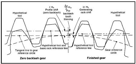 Figure 1--Hypothetical tool with zero backlash and finished gear. (Extracted from AGMA 913-A98 with AGMA permission.)
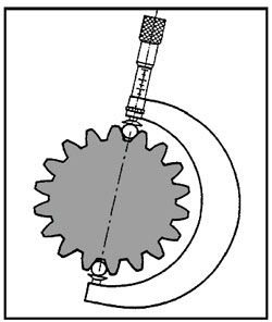 Figure 2--Tooth thickness measurement over pins. (Extracted from AGMA 2002-B88 with AGMA permission.)


 Power Transmission Engineering is THE magazine of mechanical components. PTE is written for engineers and maintenance pros who specify, purchase and use gears, gear drives, bearings, motors, couplings, clutches, lubrication, seals and all other types of mechanical power transmission and motion control components.