


Input Shaft Tradeoff Options for Single Speed Gear Reducers
EV work continues despite reduction in volume
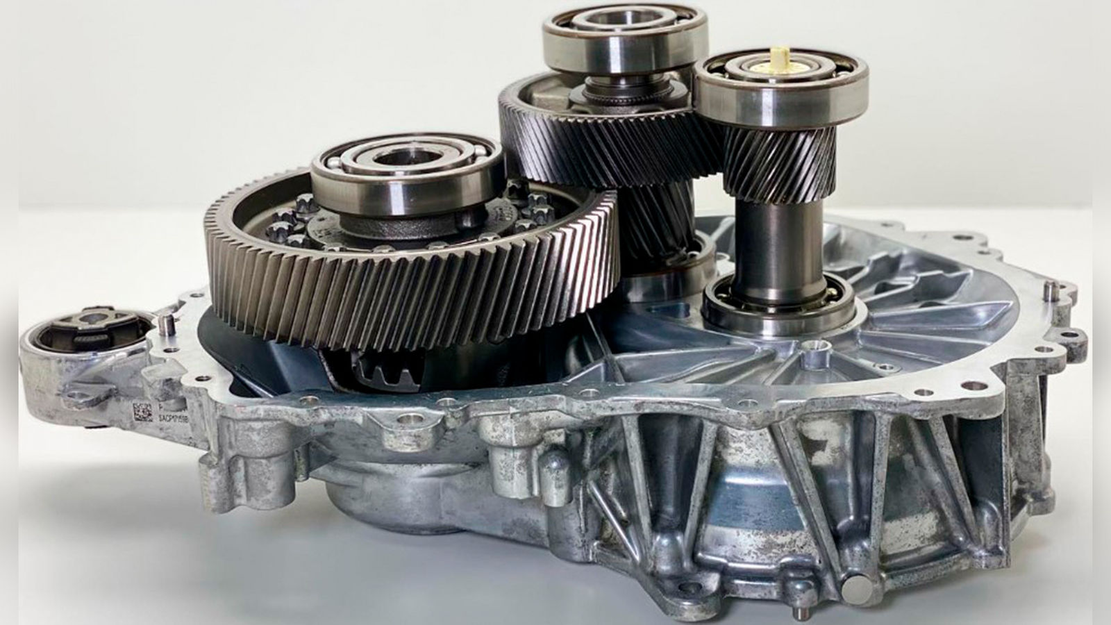
Figure 1—Photo courtesy of Munro Live on Instagram: “Partial Dissemble of the 2018 Tesla Model 3 Helical Gearbox.” Instagram, 2017, www.instagram.com/p/COiQJ1rniM1
Greetings 2026! As expected, EV demand has waned following some deregulation and tax credits being dropped as of September 2025. For us industry folks, this is simply reality catching up with the narrative. On the plus side, 2025 was a very good year for global vehicle sales–the best since 2019 (Ref. 1). A good economy can forgive many blunders. As gearbox designers, our work continues as our EV offerings are likely a permanent part of our product lineup, even if at a reduced volume. When it comes to single speed offset gearboxes, many OE’s have a similar 3 parallel shaft design, running ratios typically between 7:1 to 15:1. Some higher speed boxes are going above 20:1 ratio now, but the basic architecture is unchanged. The Tesla design shown here is a common baseline design:
There is a lot of discussion around the nuances of bearing type and placement. Here, we will look at the rotor and input shaft and discuss and compare the common alternatives.
To summarize the option we will be reviewing, we have:
- Four-bearing integrated input pinion gear (machined on shaft).
- Four-bearing splined input pinion gear.
- Three-bearing, fixed motor shaft.
- Three-bearing, fixed input gear.
- Three-bearing, single shaft.
- Two-bearing, single shaft.
For this study, we will use a nominal driving load of 100 Nm for a realistic evaluation case. All results are based on nominal fits and clearances. We will only focus on the input gear (Gear A) for misalignment since we are not evaluating any intermediate shaft effects.
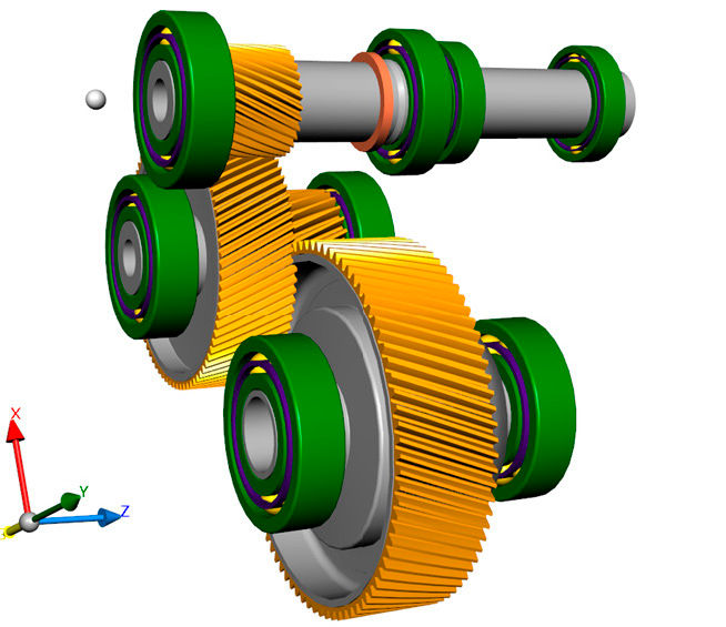
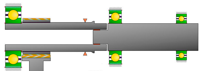
Four-bearing, integrated input pinion gear
Pro–Minimum misalignment. Able to optimize motor bearings. Easy to electrically insulate.
Con–High scrap cost on integrated pinion.
Figure 3—Four-bearing, machined pinion design.


 Power Transmission Engineering is THE magazine of mechanical components. PTE is written for engineers and maintenance pros who specify, purchase and use gears, gear drives, bearings, motors, couplings, clutches, lubrication, seals and all other types of mechanical power transmission and motion control components.