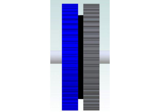
Figure 6 shows a permanent magnet located between the blue pole cap and the grey pole cap.
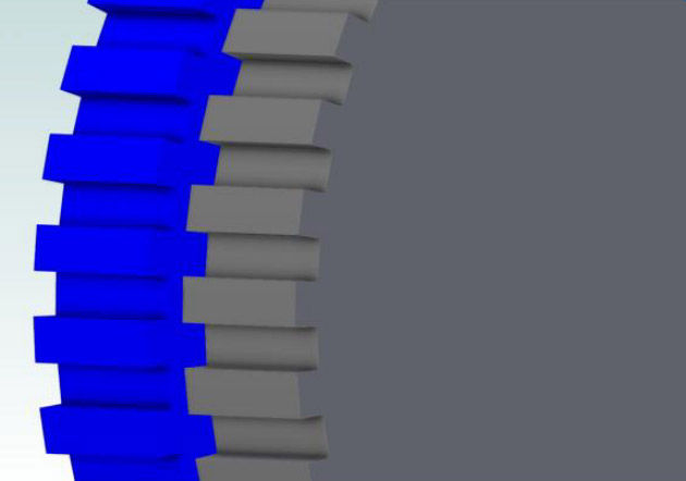
Figure 7 shows that the teeth in the blue pole cap are aligned with the gaps in the grey pole cap.
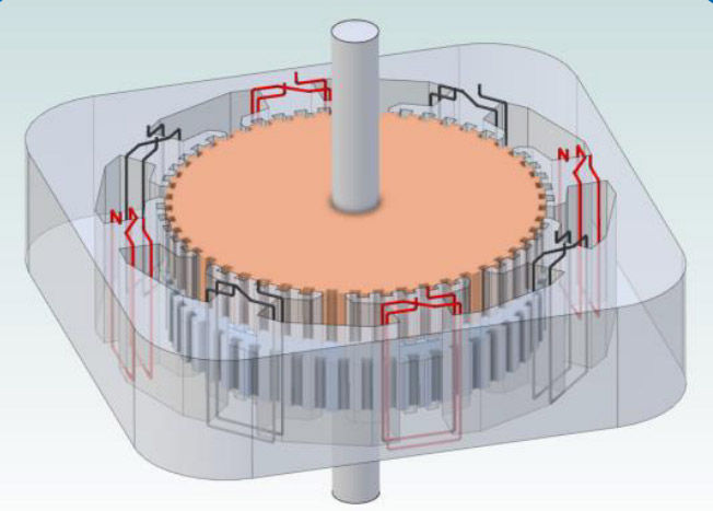
Figure 6: Rotor side view.
Figure 7: Rotor close up oblique..
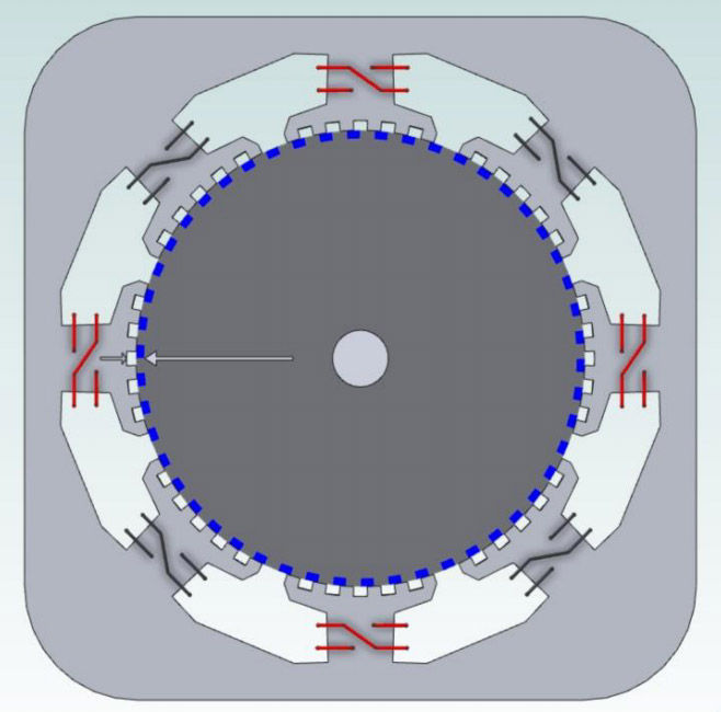
The windings at the top and bottom (12:00, 6:00) are both of the same phasing, i.e.— a positive current will cause the teeth of these phases to attract the north pole of the rotor, while those at the right and left sides have the windings connected in the reverse sense, and so will attract the south pole of the rotor. If the magnet inside the rotor (Fig. 6) is oriented so that the grey rotor cap is N and the blue rotor cap is S, then a positive current through the red windings will attract the grey teeth at 12:00 and 6:00 and while repelling the blue teeth. At 3:00 and 9:00 the stator windings have the opposite winding sense as at 12:00 and 6:00, so they will repel the grey teeth and attract the blue teeth; the result is a clockwise torque production. We will call the red windings “Phase A.”
The four black windings on the diagonal stator poles, which we will call “Phase B,” for this given rotor to stator alignment, have teeth that are balanced with respect to the rotor teeth. Energizing this Phase B in either direction will not produce torque between the stator and the rotor. Let us assume that the stator poles at 1:30 position (upper right) and at the 7:30 position (lower left) attract a north pole when energized with a positive current, while those at 4:30 (lower right) and at 10:30 (upper left) are wound in the opposite sense and will attract a south pole when energized. One can see the teeth at 1:30 and at 7:30 are mostly coupled to the blue (south pole) of rotor, while those at 4:30 and 10:30 are best coupled to the grey (north pole). Thus energizing the B-Phase while the rotor is at this position will either aid the magnet field of the rotor (is the teeth have a net field that is of the same polarity as the permanent magnet — repelling the rotor teeth), or will buck some of the magnetic field of the permanent magnet if they have the opposite polarity (i.e. attracted) to the rotor end caps.
For this instant in time that the rotor has this position, the A-phase is acting as the torque- producing quadrature phase, while the B-phase produces no torque, but can be used to strengthen or weaken the effective field strength at the rotor teeth (gap) — which is the function of the In-phase component of the driving currents.
The function of A and B reverse their roles when the motor advances 1.8 degrees mechanical, as the teeth B-phase stator poles will now be in greatest misalignment to the rotor, while those of the A-phase will be symmetrical to the rotor teeth. The I (in-phase) and Q (quadrature) components of the drive currents, must then follow the rotation of the rotor as the motor is commutated, so the static position example given for phase A and phase B at the one given position is only useful at that one position. But the same torque producing and field strengthening or weakening does apply for I and Q components as the motor is rotating.
Hopefully this gives a good physical interpretation of how field weakening occurs in a motor with an interior magnet. If the magnets are on the face of the rotor, there is not carrying of the flux from the in-phase drive component of the stator field, as the permeability of a fully charged magnet is nearly the same as air (that is, its b-h curve is saturated and the addition of additional field strength from the electromagnets of the stator are unable to significantly change the flux through the rotor magnet(s).
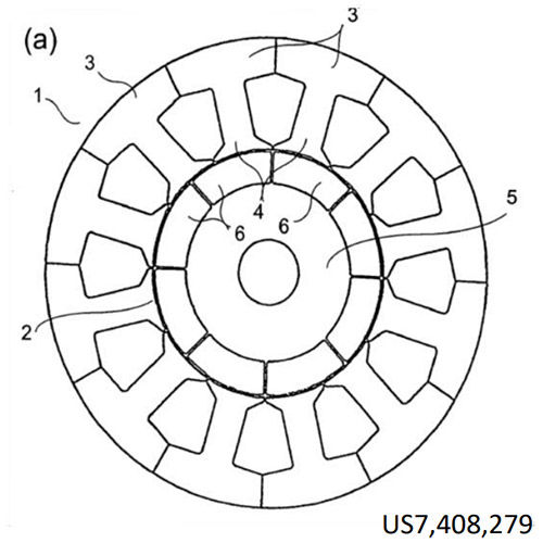
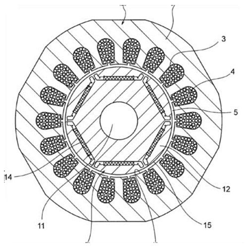
The interior permanent magnet motor design of Figure 3 also has variable reluctance coupling (saliency) between the stator and the rotor, due to the gaps and structure within the rotor, and has similar ability to do flux weakening, although it may be a bit more difficult to visualize in this structure as compared to the transverse flux design. The face-mounted magnet or Figure 2 does not have this saliency or variable reluctance; there is no high permeability magnetic material between the magnet and gap to allow flux to be captured and redirected from the I-phase component areas to the Q-phase torque-producing portions, and so this motor with face magnets is not normally able to be field weakened.
But Why Weaken the Field?
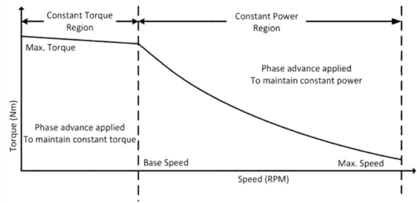
The motor generates back-EMF when the motor is in motion. The magnitude of the back-EMF is proportional to the strength of the magnetic field across the gap and the speed of the motor. The maximum speed of the motor is limited by the ability of the driver to force current into the motor windings. As the motor speed increases, the back EMF increases, and would eventually exceed the driver supply voltage. Using field weakening, the strength of gap field can be reduced, which reduces the back-EMF for a given speed. The lower back-EMF constant (torque constant) caused by the field weakening thus allows the motor to be run at a higher speed. Typically, this can double available motor speed.
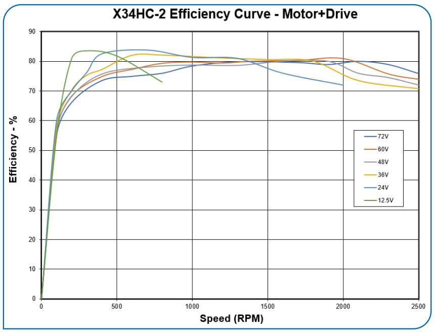
The mechanical power available at the output of the motor (including the losses from friction and windage) is the back-EMF times the quadrature portion of the winding current (cross product to be more exact). The main copper loss is the current squared times the resistance. Thus, for a given current, the best efficiency comes when the back-EMF is as large as possible as compared to the resistive I-R drop. Having the ability to vary the field strength allows the back-EMF to be kept near the maximum (power supply voltage) over a fairly wide range of speeds, which allows the motor efficiency to remain fairly high over a fairly wide range of speeds. Figure 8 shows how the efficiency can be kept high over a wide range of speeds and over a wide range of voltages. The curves show the measured combined efficiency of the motor and the driver.
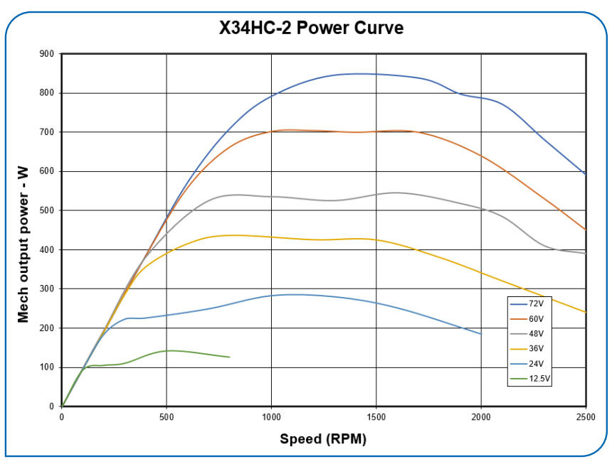
The field weakening also extends the available power curve, keeping the available power nearly constant over a two-to-one speed ratio, as seen in Figure 9. The higher available voltage allows for higher output power levels, as would be expected.
Hopefully this article has helped improve the understanding of how field weakening may be implemented in indirect permanent magnet motors — including hybrid servo motors — and why it is beneficial.
 Donald Labriola P.E. is president at QuickSilver Controls, Inc. He has been working with step motors since high school, and has had these motors operating fieldoriented closed loop control since 1984.
don_labriola@quicksilvercontrols.com