We use cookies to provide you with a better experience. By continuing to browse the site you are agreeing to our use of cookies in accordance with our Privacy Policy.
  • TOPICS
    • Design
    • Manufacturing
    • Applications
    • Components
    • Industry
    • MRO
  • MAGAZINE
    • Current Issue
    • Departments
    • Archives
    • Subscribe
    • Advertise
  • NEWSLETTER
  • VIDEO
    • Power Transmission Engineering TV
    • Webinars
  • BLOGS
    • Revolutions
    • Editors Choice
    • Motor Matters with George Holling
    • Bearings with Norm
  • BUYER'S GUIDE
  • NEWS and EVENTS
    • Product News
    • Industry News
    • Events
  • Advertising
    • Brand Awareness
      • Print: Display Advertising
      • Print: Engineering Showcase
      • Online: Web Banners & Keyword Banners
      • Online: Sponsored Content (Native Advertising)
      • E-mail: Custom, White Papers & Webinars
      • Email: Sponsored Content (Native Advertising)
    • Response & Lead Generation
      • E-Mail: Sponsored Content (Native Advertising)
      • E-mail: Newsletters
      • E-mail: Custom, White Papers & Webinars
      • Online: Buyers Guide
      • Online: Sponsored Content (Native Advertising)
    • Print
      • Print: Display Advertising
      • Print: Engineering Showcase
      • Print: MPT Expo Showstoppers (October 2023)
      • Print: Buyers Guide
      • Print: Engineering sMart
      • Print: Specifications
      • MPT Expo Show Guide Advertising
    • Online
      • Online: Web Banners and Keyword Banners
      • Online: Buyers Guide
      • Online: Sponsored Content (Native Advertising)
      • Online: Specifications
    • E-Mail
      • E-mail: Newsletters
      • E-mail: Custom, White Papers & Webinars
      • E-mail: Sponsored Content (Native Advertising)
      • E-mail: Specifications
    • Special Promotions
      • Print: Engineering Showcase
      • Print: Showstoppers (MPT Expo)
      • Print: Buyers Guide
      • Print: Engineering sMart
      • MPT Expo Show Guide Advertising
  • Contact Us
  • AGMA
    • Membership
    • Events
    • Education
    • Emerging Technology
    • AGMA Media
      • Gear Technology
      • Gear Technology India
    • Standards
Subscribe
  • Sign In
  • Create Account
  • Sign Out
  • My Account
Home » MESYS 08-2016 Available for Shaft and Roller Bearing Analysis

MESYS 08-2016 Available for Shaft and Roller Bearing Analysis

September 23, 2016

A new version of the MESYS shaft and rolling bearing analysis software including new functionality is available. The bearing analysis software allows the calculation of the load distribution within the bearing and bearing life according ISO/TS 16281 and it is integrated in a shaft system calculation with additional possibilities like modal analysis, strength calculation for shafts and interfaces to gear calculation programs.

Some general improvements include better support for HighDPI displays (multiple monitors with different DPI ratios can be used), support for 3D mouse in all 3D graphics, files can be opened via drag and drop.     

The main new features in the bearing calculation are the consideration of elastic expansion/compression for rings with clearance fit, angular cylindrical roller bearings as additional bearing types, track roller calculation with elastic outer ring now also supported for double row tapered roller bearings, load spectra for track rollers can consider loading on multiple points, new 2D view for the load distribution showing the pressure distribution on the raceway, custom setting for rolling element temperature and the import of additional encrypted bearing databases.

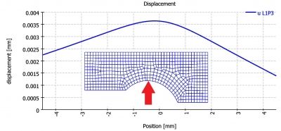
If a bearing ring of an angular contact ball bearing is mounted with clearance and pretension is applied the ring can expand until it makes contact with the housing. This affects the stiffness of the bearing. This effect is now considered by a simplified approach on the basis of thick ring theory. The elastic expansion of a ring under pressure is considered on bearing clearance. The calculation currently uses Dpw+Dw as inner diameter for the outer ring without consideration of the shoulders and allows an additional stiffness factor as input. So without the stiffness factor the ring will be too soft in the calculation and the expansion will be a little too large.

The attached image shows a comparison for one example. The bearing calculation uses an expansion of 3.86 μm while an axisymmetric FEA would lead to a maximum value of 3.68 μm. So the stiffness factor could be chosen to 1.049 to correct this error. Taking into account that all parameters have tolerances an error below 1 μm could be ignored in most cases.

Shaft calculation features include new graphic windows for bearing overviews shows the same graphic for all bearings in a system,  CAD import of shaft geometry as 2D DXF or 3D Step, CAD export of geometry as 3D Step, import of 3D Housing as Step file which can be connected to the supports in the system, new calculation method for harmonic response, global setting for Rayleigh-damping, shaft geometry shown as background image in diagrams, optional measurement lines for forces and supports in 2D view of shaft geometry.

Images are often helpful to understand the behavior of a shaft system. Instead of graphics for each bearing only, the shaft calculation now also offers overview graphics with information for all bearings in one view.

Usually the input of shaft geometry as cylinder and cone elements is quickly done, but there had been requests for import of shaft geometry from CAD files. An import from 2D DXF or 3D Step files was added for version 08-2016.

Importing geometry from CAD format can lead to many small elements if, for example, many relief grooves are considered. Therefore, it might be helpful to disable some features in the CAD system before export. The shaft calculation considers only axial symmetric geometry, so only the geometry in the x/y-plane is imported from a 3D step file. 

A housing can be imported as step file and considered as stiffness in the calculation of the shaft system. The CAD model will be meshed and reduced to a stiffness matrix automatically.

An axisymmetric part can be defined using a polygon. It will be meshed and the stiffness can be considered with the shaft model. Selected faces or edges of the 3D part can be connected to a shaft support. These models can be used in special cases where a beam could be too stiff.

Product News
  • Related Articles

    Mesys AG Will Present New Shaft and Bearing Analysis Software at Hannover Messe

    MESYS Software Version 06/2022 is Available

    MESYS Offers Latest Version of Shaft and Bearing Calculation Software

Free Power Transmission Engineering Subscriptions
Subscribe
Free Power Transmission Engineering Subscriptions
Subscribe
FEATURED VIDEO
  • Sugar Refinery Dryer Fan with NSK Europe
March 1, 2023
RECOMMENDED
  • First Impressions

    March 15, 2023
    IFPE6.jpg
  • Asset Management in Manufacturing

    February 7, 2023
    pt0223_Page_18_Image_0001.jpg
  • Vesconite Marine Rudder Bearings

    February 7, 2023
    pt0223_Page_28_Image_0001.jpg
  • The High Demands of Off-Highway Drive Systems

    March 21, 2023
    pt0323_Page_35_Image_0001.jpg
  • Making the Move to Digitalization and Electrification

    March 21, 2023
    pt0323_Page_25_Image_0002.jpg
  • The High Demands of Off-Highway Drive Systems

    March 21, 2023
    pt0323_Page_35_Image_0001.jpg
  • Making the Move to Digitalization and Electrification

    March 21, 2023
    pt0323_Page_25_Image_0002.jpg
  • First Impressions

    March 15, 2023
    IFPE6.jpg
  • Subscribe
  • Advertise
  • Contribute
  • Gear Technology
Powered byAGMA
Copyright © 2023 Power Transmission Engineering
  • Privacy Policy
  • Contact