[advertisement]
Technical Articles

June 4, 2025


Norm Parker


Automotive Vehicles Bearings Roller Bearings Variable Frequency Drives Technical Articles Transportation Revolutions

The Path of Least Resistance—Roller Bearing Damage in VFDs

Bearing damage due to electric current in variable frequency drives (VFD) is well understood as a general concept. What is not yet fully developed are the models that better predict when a system is at risk and where we should be looking for early signs of damage.

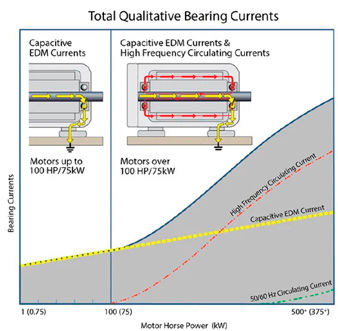
Aegis (grounding rings) has, for years, provided great documentation outlining the need for an insulated / conductive pairing in VFDs due to various currents involved. In the chart below, shaft voltage discharge and high frequency circulating currents are typically what we are looking for.

Figure 1—Aegis Handbook 4th Edition p. 4.

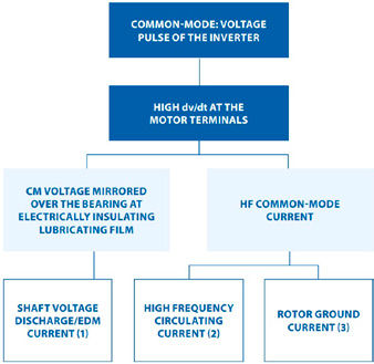
Rotor to ground current is often damage caused by an improperly grounded test cell.

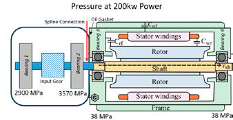
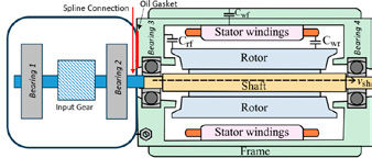
The schematic below (Figure 2) provides a useful visual in understanding circulating current vs shaft voltage.

Figure 2—Current Paths AEGIS (6).

Adding the primary shaft of the gearbox to the image above and it becomes apparent that without mitigation, shaft voltage could be carried into the gearbox side bearings. It is less likely that circulating current would make it to the gearbox side as the path would need to include going through a gasket or bolts connecting the cover and housing.

Figure 3—Layout of Motor + Input Gearbox Shaft.

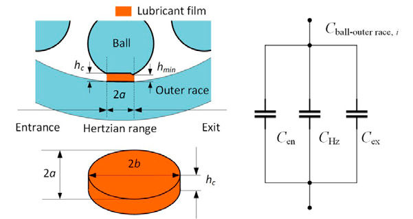
To understand where the current would likely travel with an unprotected system, we must understand the loading conditions. The primary protection for bearing current is the lubrication film in each bearing. The thicker the film, the higher the capacitance. Film thickness is determined by temperature, speed and load—and other minor contributors such as age of oil, surface finish and specific grades of steel. With a connected main shaft like this, our problem is greatly simplified because speed among the bearings is the same and we can assume temperature is similar—at least at the bearing race locations. Now we just need to understand loading conditions. Though various proposals for formulas exist, generally everyone agrees with some form of the relationship:

Image 1—Bearing Failure from an improperly grounded test cell.
Share and save:


This article appeared in the June 2025 issue.


Read PDF

[advertisement]

One such model describes as:

Figure 4—Bearing Capacitance Model: University of Kentucky (4).


Figure 5—Film Thickness vs. Temperature, Load, Speed.

Running a few different scenarios through a full model gives us an intuitive relationship between the three primary drivers of fluid film thickness. Increasing temperatures reduces oil viscosity and reduces film thickness as a result. Increasing load reduces film thickness as the race and balls are forced together. Increasing speed increases film thickness as the hydrodynamic pressure increases.

The Hertzian range or ellipse is a function of the applied load and bearing geometry. This is directly proportional to the resulting pressure of each ball. Considering each ball in the load zone has a different load/pressure and every bearing has a unique geometry, we can see this problem can become quite complex. However, if we only look at the maximum pressure of each bearing in our simplified model, it becomes easier to understand.

Figure 6—Bearing Pressures at 200 kW.

If we assume our capacitance model is correct and we have enough shaft current to damage a bearing, we can see that, under load, there is potential for the current to travel through Bearing 2 as it has the highest pressure.

We now have some ideas of where to concentrate our efforts in looking for bearing damage to see if we have early sign of electrical damage. This is not just limited to the motor bearings, but also in the adjacent gearset bearings.

It is important to understand that not all electrical damage looks the same. We can see everything from a minor dulling of ball sheen to full tactile—audible noise—fluting.

Figure 7—A Range of Ball Conditions: 7a (new), 7b (light dulling), 7c (opalescent).


Figure 8—Heavy tactile fluting on motor bearing (picked up on vibration sensor).


Figure 9—Outer Race of Electrically Damaged Motor Bearing.

Does the theory match reality? Can stray motor currents find their way to the gearbox? They absolutely can. In real testing with unprotected motor and gearbox bearings, a unit was exhibiting gearbox bearing noise signals. Upon inspection, Bearing 2 had clear indications of light fluting (could not feel with bare skin, but was picked up on vibration) along with the elusive “tiger stripes” found on the input gear.

Figure 11—Tiger Striped Input Gear.
Figure 10—Light Fluting on Bearing 2.
Figure 11—Tiger Striped Input Gear.
[advertisement]

Finding these early signs of damage gave an early clue that our gearbox was not properly protected and allowed adequate time to implement the corrections. Had these indications not been found early on by looking at the gearbox side, it could have risked launch timing down the road.

Conclusion

Any traction motor can pose a risk to unprotected bearings—though typically, severe damage is more common with motors above 100 kW. Depending on the overall power and individual motor characteristics, sometimes just a grounding ring OR an insulated bearing on the non-drive side of the motor is adequate protection. In higher power motors, both an insulated bearing on the non-drive end of the motor and a grounding ring on the drive side of the motor may be needed. Both are costly upgrades, so it is tempting to avoid adding the needed upgrades. At the very least, ensure you are package protected for a grounding ring and have a plan for implementation if or when it is needed. Many electrical damage signs may not manifest at lower temperature testing as the oil is thicker and may be enough to protect the bearing. Likewise, simply spinning an unloaded motor at high speeds may mask future potential issues. It is imperative that you test under high-load and high-temperature conditions to determine if the system is at risk.

References

  1. Steffen Puchtler, et al. “Analyzing Ball Bearing Capacitance Using Single Steel Ball Bearings.” Tribology Letters/Tribology Letter, Vol. 71, No. 2, 27 Feb. 2023, https://doi.org/10.1007/s11249-023-01706-7. Accessed 28 June 2024.

  2. “Industrial Bearing Protection Handbook 4th Ed.” Aegis, 2024 Electrostatic Technology, Oct. 2024, www.est-aegis.com/. Accessed 25 Apr. 2025.

  3. He, Feng, et al. “Electrical Bearing Failures in Electric Vehicles.” Friction, Vol. 8, No. 1, 23 Jan. 2020, pp. 4–28, https://doi.org/10.1007/s40544-019-0356-5.

  4. “Modeling of Bearing Voltage in Electric Machines Based on Electromagnetic FEA and Measured Bearing Capacitance.” University of Kentucky UKnowledge, Power and Energy Institute of Kentucky, 25 June 2021, uknowledge.uky.edu/cgi/viewcontent.cgi?article=1068&context=peik_facpub. Accessed 25 Apr. 2025.

  5. Endika. “Advanced Power Inverter Topologies and Modulation Techniques for Common-Mode Voltage Elimination in Electric Motor Drive Systems.” Science Direct, Elsevier, 26 Jan. 2021, doi.org/10.1016/j.rser.2021.110746. Accessed 28 Apr. 2025.

  6. “Motor Bearings: Electrical Damage Simplified - a Further Examination and Clarification.” Aegis, ITW, 2017, blog.est-aegis.com/motor-bearings-electrical-damage-simplified-examination-clarification. Accessed 25 Apr. 2025.

[advertisement]

×

Like What You see?

Power Transmission Engineering magazinePower Transmission Engineering is THE magazine of mechanical components. PTE is written for engineers and maintenance pros who specify, purchase and use gears, gear drives, bearings, motors, couplings, clutches, lubrication, seals and all other types of mechanical power transmission and motion control components.

E-mail

Choose at least one from the options below:

 Power Transmission Engineering magazine, published 8 times per year (print or digital).

 Power Transmission Engineering e-mail newsletter, published weekly.

 Special Offers and promotions via e-mail from Power Transmission Engineering's advertisers and partners.

*Unsubscribe any time.
Full details in our privacy policy
Already a subscriber? Log in