


Safe, Reliable Spindle Operation
Development of a load limit diagram for a motor spindle using MESYS
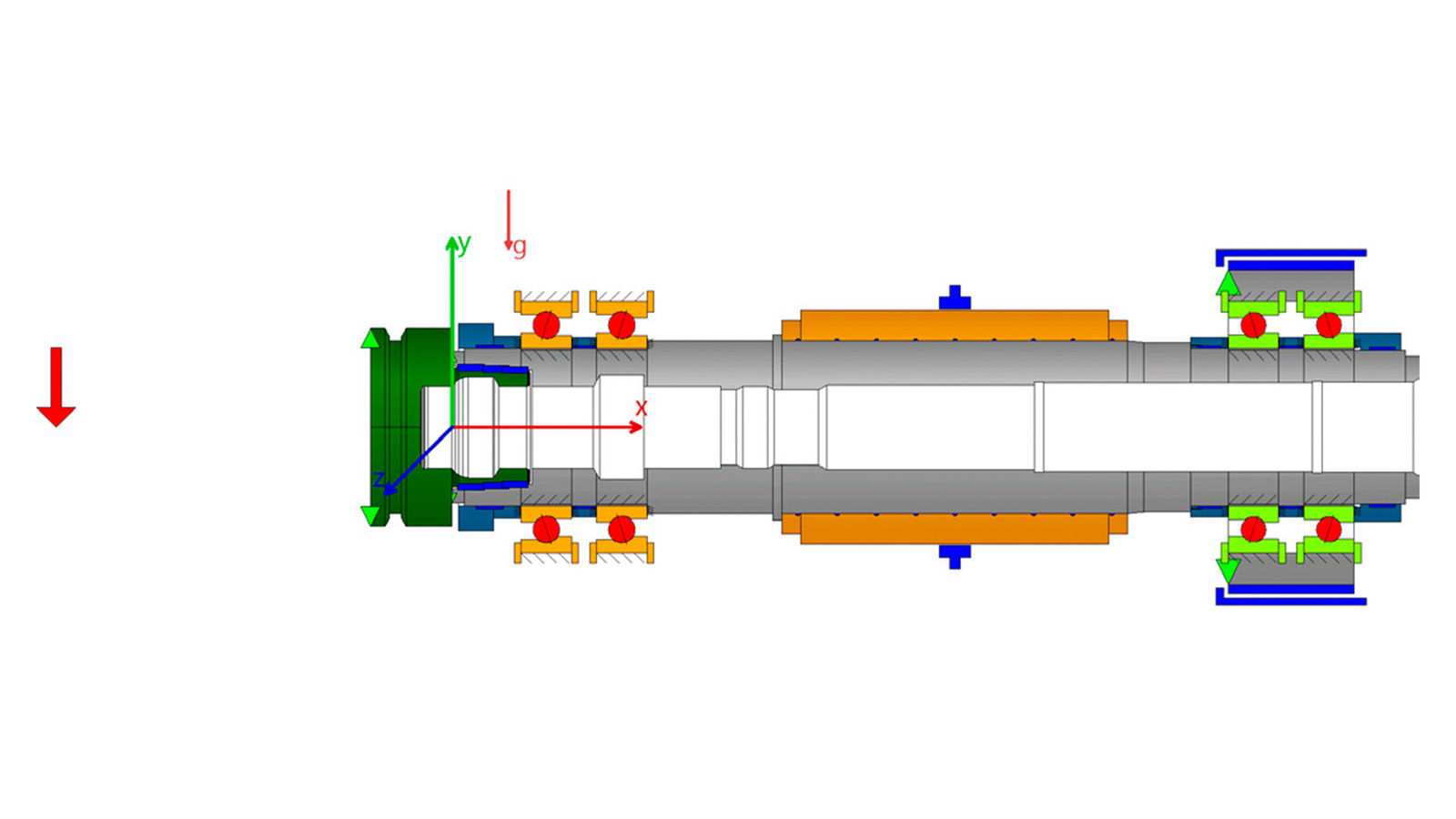
Figure 1—Motor spindle.
The load limit diagram of a motor spindle serves to graphically represent the permissible operating range as a function of parameters such as rotational speed. It enables a quick assessment of the conditions under which the spindle can be operated safely and reliably without exceeding mechanical, thermal or dynamic limits. Such a diagram is a key tool for the design, selection and evaluation of spindle systems in mechanical engineering particularly in the field of machining where high demands are placed on precision, performance and service life.
The same methodology can also be applied to electric motors in general, where torque, speed, thermal and structural limits likewise play a central role in design and application. Whether in machine tools, robotics, automotive engineering or industrial drives—a systematically developed load limit diagram provides a solid foundation for the safe and efficient use of the motor at its intended operating point.
To better understand these interrelationships, this article aims to explain the systematic derivation of a load limit diagram. It addresses both the physical fundamentals and the practical limitations arising from bearing arrangement, drive system, cooling and structural design. The objective is to identify the key influencing factors that determine the spindle’s limit behavior and to present them in a transparent, simulation-based format using MESYS.
Specification:
The investigated hypothetical application is a high-speed motor spindle for aluminum machining, with a maximum torque of 10.75 Nm and a maximum rotational speed of 36,000 rpm. An HSK-F63 interface is used as the tool holder. The applied tool radius is r = 12 mm, corresponding to an end mill with a diameter of 24 mm.
Bearing Concept:
The spindle is supported by two spring-preloaded O-arranged tandem bearing sets, each consisting of a front and a rear bearing pair. The following bearing configurations are used:
- Front bearing pair: 7010, contact angle = 18°
- Rear bearing pair: 7010, contact angle = 18°, spring-preloaded with 1,300 N


 Power Transmission Engineering is THE magazine of mechanical components. PTE is written for engineers and maintenance pros who specify, purchase and use gears, gear drives, bearings, motors, couplings, clutches, lubrication, seals and all other types of mechanical power transmission and motion control components.