Harmonic drive (or strain-wave) gearheads use a rigid circular spline and thin flexible spline (flexspline) with an elliptical wave generator which is normally the driven input surrounded by a flexible bearing which presses on the flexspline, causing the flexspline to be stretched so that teeth of the flexspline engage with the rigid circular spline around the region of the two stretched portions of the flex spline. The teeth are carefully designed to allow as much contact area as possible while also allowing them to pass each other without (with minimal) rubbing. A cup structure is generally attached to the flexible spline. The output is the difference in position between the two splines, with one generally fixed and the other used as the output (although these can have both rotating and the input adjusted to produce a phasing adjustment, such as are used on large printers). One rotation of the elliptical input causes the flexspline to advance by one tooth on each half of the rigid spline. The large contact diameters and the multiple engaged teeth allow for very stiff gearheads, with a single stage gear ratio of capability of approximately 50 to several hundred with a typical efficiency of around 60%. Harmonic drives can also be designed with zero backlash. The contact and the flexure does limit the life of the gearhead, but with proper lubrication life expectancy is good. The high stiffness and zero backlash and high gear ratios makes these popular with robotic arms.
Cycloidal Gearhead
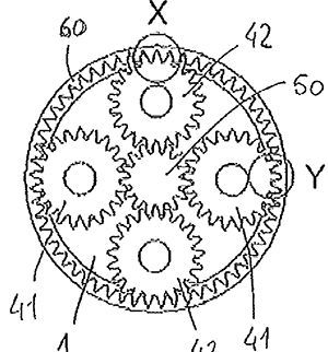
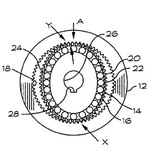
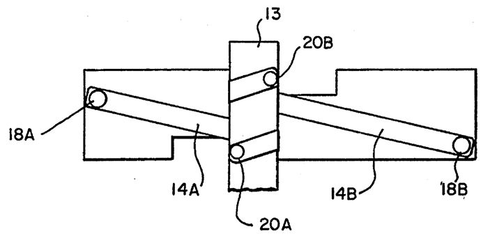
Figure 4: Cycloidal Gearhead.
Cycloidal gearheads use an eccentric mechanism to walk one (or more) cycloidal gears around a series of pins. A rotation of the eccentric moves the cycloidal gear in a small circular motion that moves the point of engagement with the outer ring forward by one pin for each revolution of the eccentric. The output shaft is normally driven from the outer ring (into which the pins are mounted. Other arrangements may use alternatives to replace the pins, but pins with rollers help reduce the contact friction. The large number of pins in contact with the cycloidal gear produce a gear design with low backlash and very high impact rating and high continuous torque rating. The contacts are all rolling so efficiency is fairly high (90–95% per stage) and wear is low. The use of two (or more) cycloidal gears operating in opposition helps reduce vibration from these moving masses while also increasing the number of pins in contact to increase the torque rating and stiffness. The gear ratio for a single cycloidal stage can go up to approximately 119:1 per stage. These are also used in robotic applications for their high stiffness and high gear ratio.
Combined Stages
It is very common to combine different gearhead styles. For example, to use a planetary gearhead followed by one of the higher torque rated harmonic or cycloidal gear head stage, taking advantage of the best of each.
Rotary to Linear
A large percentage of motors are rotary while many of the applications require linear motion. Here are a few of the common choices to use a rotary motor to make a linear motion.
Lead Screws
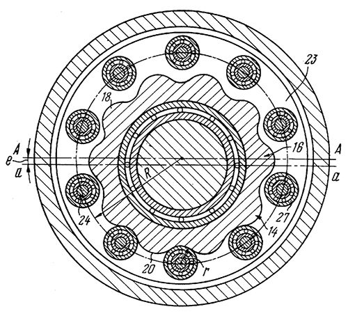
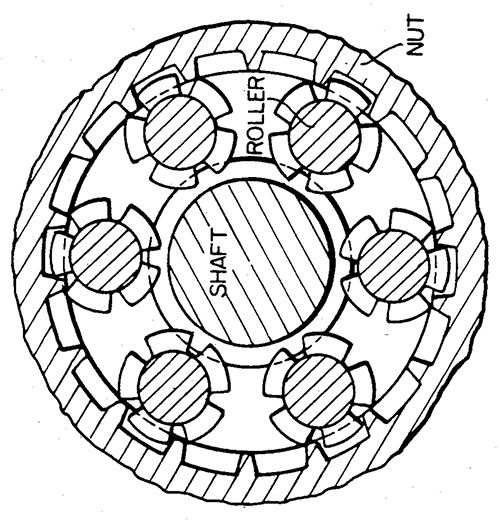
Figure 5: Planetary Roller Leadscrew.
Lead screws have a wide range of pitches producing a wide range of effective “gearing”. Leadscrews with a higher pitch can be back driven and those with a very tight pitch can be locking (not able to be backdriven). Tight pitches can be used with a single stage to move quite heavy loads. The effective “lever arm” when calculating reflected inertia to the motor rotary inertia is the pitch per revolution divided by 2×Pi. A 2 mm pitch leadscrew has an effective “arm” radius length of 318um — that is moving a 1kg load would reflect an inertia of 1kg × (318e-6 m)2 = 1e-7 kg-m2 making a easy inertial match for even a fairly small motor. The trade off is the maximum speed is limited by the motor speed allowable for the bearing and by the maximum speed of the leadscrew to avoid whipping of the leadscrew (critical speed). Higher pitches can significantly speed the motion. Leadscrews are well applied to heavier loads with lower speeds. Multi-start lead screws can produce fast motion while still having a smaller thread spacing on the leadscrew. A 2 mm pitch 6 start lead screw advances 12 mm per revolution. This is an effective arm radius of 12 mm/ (2×Pi) = 1.91 mm; a 1 kg mass would be reflected as 3.6e-6 kg-m2. For reference a typical short stack NEMA 23 step motor has an inertia of 1.5e-5 kg-m2 so a 1kg payload still is 4× less inertia than this size of motor.
Variants include brass and plastic lead nuts, and ball lead screws, that trade speed, noise levels, and life expectancy. There are also planetary roller lead screws that use other counter-rotating leads instead of nuts. These have very high force capability with much less wear as the sliding friction has been replaced with rolling motions.
Rotary motors are available with leadscrew shafts to reduce the size of the assembly and to eliminate couplers and bearings. Alternatively, there are also hollow motors that have a lead nut which is rotated by the motor for use with a stationary lead screw, which eliminates whipping of the leadscrew.
Belt Drives
Belt drives, helical belt drives, and wire drives convert the rotary motion of a pulley into a linear motion. Typically tooth belt is passed around a matching tooth pulley to avoid slippage. Wire drives can secure both ends of the wire to a bobbin with sufficient wraps to cover the required distance, while a helical belt drive typically uses a flat typically stainless steel belt wound in similar method to the wire drive.
Figure 6: Helical Belt Drive.
The effective lever arm is the radius of the pulley, which can be significant. The linear motion per revolution is 2×pi× the pulley radius, which can make for significant speeds. With the higher speed does come a higher reflected inertia, but a stiff belt can keep the resonance frequency high enough for a tight, quick closed loop motion. Note that the motor can be fixed and the belt moving, or the belt fixed and the motor carried on the payload. A 20 mm pulley would have a radius of 10 mm; that same 1 kg load now reflects 1e-4 kg-m2 with a motion of 62.8 mm/revolution. Belt drives are commonly used for lighter loads needing rapid motion.
Rack and pinion
A rack and pinion acts much like a steel belt drive — the rack taking the place of the belt and the pinion gear replacing the pulley. Light rack and pinions can be directly driven by a motor, although gearing before the pinion gear is common for heavier loads. The rack typically has a much higher stiffness. As there is little give, care needs be taken to control the load between the pinion and rack to keep backlash reasonable. The high stiffness results in the capability for very high forces and very high speed operation.
Linear Motors
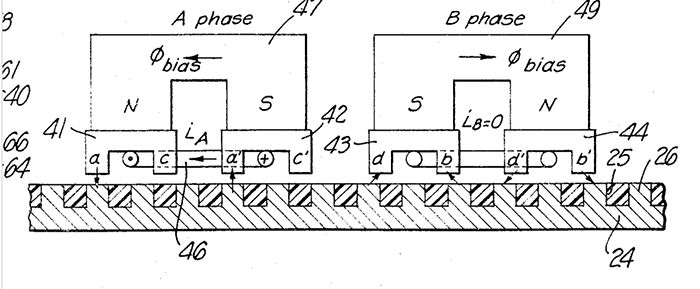
There are multiple linear motors that directly generate thrust without the need to convert a rotary motion. The Sawyer motor is a linear step motor that runs on a planar platen. The platen made of a high permeability material into which slots have been cut and filled with low permeability material (like epoxy) and ground to make a flat surface. The head carries both the magnets and the coils which are used to energize the motor. The sawyer motors are also available in XY configurations, even with limited rotary capability. This gives a direct XY capability without any rotary conversion.
Figure 7: Sawyer Planar Motor.
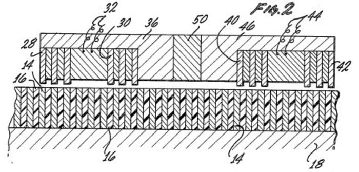
There are also linear motors that directly move a pusher rod in and out. These are available in both sawyer type (magnets and coils on the driver) and conventional with stacked NSNS…NS magnets in the rod, with corresponding drive coils for higher force and velocity capability. Some of these rod type motors also include hall effect sensors to provide closed loop position capability.
Figure 8: Linear Step Motor.
There are even motors that combine two motor stages to provide both the rotary and linear capability for a Z-Theta capability.
Although this article touches just a small bit of the art in attaching motors to loads, focusing on small and servo motor applications, there are many ways to accomplish motion and it is often worthwhile looking at the options.
Figure 9: Linear + Rotary Step Motor.
 Donald Labriola P.E. is president at QuickSilver Controls, Inc. He has been working with step motors since high school, and has had these motors operating fieldoriented closed loop control since 1984.
don_labriola@quicksilvercontrols.com


 Power Transmission Engineering is THE magazine of mechanical components. PTE is written for engineers and maintenance pros who specify, purchase and use gears, gear drives, bearings, motors, couplings, clutches, lubrication, seals and all other types of mechanical power transmission and motion control components.