We use cookies to provide you with a better experience. By continuing to browse the site you are agreeing to our use of cookies in accordance with our Privacy Policy.
  • TOPICS
    • Design
    • Manufacturing
    • Applications
    • Components
    • Industry
    • MRO
  • MAGAZINE
    • Current Issue
    • Departments
    • Archives
    • Subscribe
    • Advertise
  • NEWSLETTER
  • VIDEO
    • Power Transmission Engineering TV
    • Webinars
  • BLOGS
    • Revolutions
    • Editors Choice
    • Motor Matters with George Holling
    • Bearings with Norm
  • BUYER'S GUIDE
  • NEWS and EVENTS
    • Product News
    • Industry News
    • Events
  • Advertising
    • Brand Awareness
      • Print: Display Advertising
      • Print: Engineering Showcase
      • Online: Web Banners & Keyword Banners
      • Online: Sponsored Content (Native Advertising)
      • E-mail: Custom, White Papers & Webinars
      • Email: Sponsored Content (Native Advertising)
    • Response & Lead Generation
      • E-Mail: Sponsored Content (Native Advertising)
      • E-mail: Newsletters
      • E-mail: Custom, White Papers & Webinars
      • Online: Buyers Guide
      • Online: Sponsored Content (Native Advertising)
    • Print
      • Print: Display Advertising
      • Print: Engineering Showcase
      • Print: MPT Expo Showstoppers (October 2023)
      • Print: Buyers Guide
      • Print: Engineering sMart
      • Print: Specifications
      • MPT Expo Show Guide Advertising
    • Online
      • Online: Web Banners and Keyword Banners
      • Online: Buyers Guide
      • Online: Sponsored Content (Native Advertising)
      • Online: Specifications
    • E-Mail
      • E-mail: Newsletters
      • E-mail: Custom, White Papers & Webinars
      • E-mail: Sponsored Content (Native Advertising)
      • E-mail: Specifications
    • Special Promotions
      • Print: Engineering Showcase
      • Print: Showstoppers (MPT Expo)
      • Print: Buyers Guide
      • Print: Engineering sMart
      • MPT Expo Show Guide Advertising
  • Contact Us
  • AGMA
    • Membership
    • Events
    • Education
    • Emerging Technology
    • AGMA Media
      • Gear Technology
      • Gear Technology India
    • Standards
Subscribe
  • Sign In
  • Create Account
  • Sign Out
  • My Account
Home » Blogs » Bearings with Norm » Ball Bearing Inner Ring Fits and Creep (Part 2)

Bearings with Norm
Bearings with Norm RSS FeedRSS

Bearing Failure / Bearing Life / Bearing Lubrication / Efficiency / Energy Efficiency / Life / Load / Automotive / Electric Vehicle / Electrification / E-Mobility / Bearings / Electric Motors / Technical Articles
Norm parker profile pic

Norm Parker is currently Technical Fellow at Stellantis. He has contributed articles to PTE since 2014.

Ball Bearing Inner Ring Fits and Creep (Part 2)

April 6, 2023
Norm Parker
pt0423_Page_48_Image_0001.jpg

Figure1—Differential hub cracking on high load test due to wear of material from insufficient press fit.

Welcome back to Part 2 of our inner ring and creep discussion. We left off with our creep calculation resulting in a 10.5 µm minimum inner ring fit to avoid creep. For the sake of making clean dimensions, let’s call it 10 µm on the lower end and the upper end is simply whatever your manufacturer can hold. For the 6205, something around 20–25 µm tolerance range would be expected. Often this can be accomplished with hard turning alone. Surface finish is not too critical here. Most bearing manufacturers will recommend a 0.8 Ra for small bearings and 1.6 Ra for large bearings, without clearly defining what a large bearing is. The main consideration for surface roughness is that if the surface is too rough, the peaks of the material will plow off during the bearing press resulting in less of a press fit than intended.

pt0423-pg46-1.jpg

Figure 2—NSK Rolling Bearings E1102k c.19.

Now we consider our shaft tolerance range of 10–20 µm. If we review the standard shaft fit chart in Figure 2, we see that this custom range falls between m6 and n6.

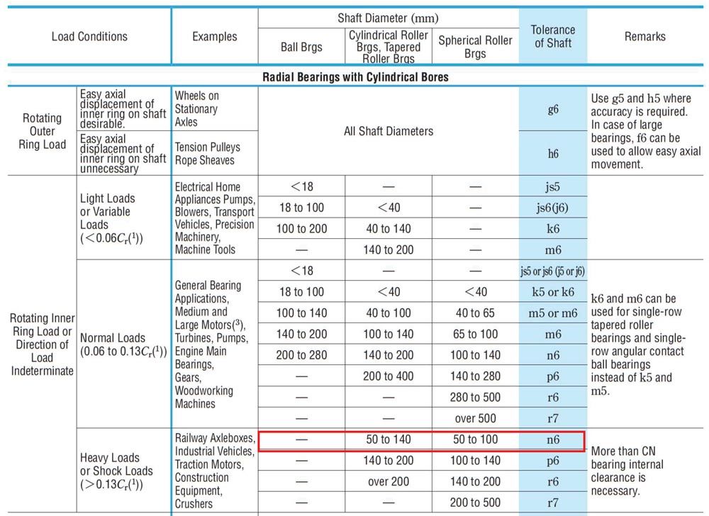
If we review our standard fit table in Figure 3, you will notice on the load condition column that a Heavy Load is defined as > 13 percent of the dynamic load rating Cr. We have designed our creep loads for 50 percent of Cr, so falling near the n6 range makes perfect sense. Applying these fits is very easy. The 6205 inner ring bearing tolerance is 25 0/-0.010 mm. Bearings are usually written in negative unilateral tolerances like this. The nominal diameter (what we call it by), 25 mm is the largest diameter. We size our shaft by taking the bearing nominal bearing diameter and applying the fit tolerances. Our shaft diameter is simply 25.01–25.03 mm.

Now let’s see how we use this value for our internal clearance. For this example, we will look a solid and hollow shaft. Most of the large bearing manufacturers have a fit tool on their website. I like Koyo’s, it is easy to use and customize, they include both 3 sigma and min-max methods.

pt0423-pg46-2.jpg

The 3-sigma method can be useful if you have confidence that your parts will follow a normal distribution. If you expect to see parts at the limits, you may prefer the min-max method which uses the true limits of the parts. You can usually rely on bearings falling within the center 50 percent of the tolerance range. If we say that we want to the 3-sigma method to stay above zero, our solid shaft falls a little off by 2.7 µm. This is an easy enough fix by dropping the shaft diameter by ~ 3 µm, but recall, that number was set for a reason, creep. This is the game we have to play. Revisit your creep calculations and see what that does for your operating load. Perhaps it only affects a very small portion of your cycle, or it may cut into a high load test that you need to avoid creep on. Effective clearance includes temperature conditions which we aren’t worrying about right this minute.

pt0423-pg47-1.jpg

Figure 3—NSK Rolling Bearings E1102k Fit Table A85.

pt0423_Page_49_Image_0019.jpg

Figure 4—koyo.jtekt.co.jp/en/calculation/operating_clearance/?pno=6205

pt0423_Page_50_Image_0002.jpg

Figure 5—Internal Clearance Results for solid shaft.

Now I take this exact same calculation and add a 15 mm through hole to the shaft (5 mm wall thickness if you prefer) and look how dramatically the clearance changes. I get almost 7 µm of internal clearance back due to the shaft compliance. Recall in the previous article, I mentioned that I often assume a 1 class higher fit for hollow shafts—this is the reason.pt0423_Page_50_Image_0001.jpg

Figure 6—Internal Clearance Results for hollow shaft.

Ok, I’m going to leave you with that to stew on for this article. I have a blast with shaft and housing fits; I find this an enjoyable part of the job. It is often challenging, there is often not a perfect answer. You will find yourself with simultaneous problems of not hitting your creep numbers and having high hoop stress and pushing your clearance to the limits. I hope I can talk you into enjoying this process rather than losing sleep over it. Think of this like being a meteorologist and learn to confidently say that we have a 50 percent chance of rain. Until next time, enjoy!

Recent Comments

Good advice, so are the big majors rebranding...

Free Power Transmission Engineering Subscriptions
Subscribe
Free Power Transmission Engineering Subscriptions
Subscribe
FEATURED VIDEO
  • Tamturbo1
    SKF and Tamturbo cooperation
August 17, 2022
RECOMMENDED
  • Industrial Transformation at Hannover Messe

    April 6, 2023
    pt0423_Page_32_Image_0002.jpg
  • Precision Coupling Basics—Stiff or Stiff Enough?

    April 6, 2023
    pt0423_Page_34_Image_0001.jpg
  • Peering into the Crystal Ball on Condition Monitoring Technology

    March 21, 2023
    pt0323-pg30-1.jpg
  • KISSsoft Supports Student Racing Team in Taiwan

    April 6, 2023
    pt0423_Page_40_Image_0001.jpg
  • Having a Ball: The Technology Behind the Ball Drop

    April 6, 2023
    pt0423_Page_22_Image_0001.jpg
  • KISSsoft Supports Student Racing Team in Taiwan

    April 6, 2023
    pt0423_Page_40_Image_0001.jpg
  • Having a Ball: The Technology Behind the Ball Drop

    April 6, 2023
    pt0423_Page_22_Image_0001.jpg
  • Industrial Transformation at Hannover Messe

    April 6, 2023
    pt0423_Page_32_Image_0002.jpg
  • Subscribe
  • Advertise
  • Contribute
  • Gear Technology
Powered byAGMA
Copyright © 2023 Power Transmission Engineering
  • Privacy Policy
  • Contact