A Backward Glance at TPS 2024
October 2, 2024


Well, I am happy to be back here at PTE! It has been a few years since I have been able to write casually due to some legal structures in my company. Coincidentally, those barriers were removed not long before PTE Sr. Editor Matt Jaster reached out to me to ask if anything had changed with my disposition. Additionally, I recently started working on a couple of topics with ABMA (now managed by AGMA), which I won’t get into just yet, and then discovered through Matt that AGMA and PTE have also joined ranks. What a great combination, very exciting developments in bearing land, indeed!
While we have been out of contact, COVID has been running almost in parallel with the unprecedented electric revolution in the automotive industry. When the COVID shutdowns started, I thought we had—maaaybe—five years before everything looked like a post-nuclear apocalypse out of a movie. Somehow, in a page out of bizarro-land, this electrification wind sprint started around the same time as COVID and made us all busier than ever!
Electrification has really brought ball bearings back into focus as the primary bearing in our drive systems. Some boxes have tapers on the slower shafts for stiffness and others are using a ball/cylindrical combo for efficiency. Regardless, we all face the same challenge on the primary shaft in dealing with the potential of 18,000–20,000+ rpm speeds coming out of the motor. Plenty of applications run 20,000 rpm; what makes the automotive motor unique is, in addition to speed, we are driving huge torques, frequent torque reversals and a huge range of temperatures both internally and geographically. Of course, this all needs to be suited for high-volume manufacturing as well. Adding full ceramic balls, a PEEK cage and a high precision classification is a really easy way to run greater than 20,000 rpm all day but is an expensive option. One bearing alone could hurt the cost competitiveness of your gearbox. In the case where a single bearing can change the landscape of your project, it is worth taking a little time to understand exactly what the drivers of our speed limitations are.
Due to the extensiveness of this subject, we will only discuss catalog Limiting Speed today which is a mechanical based speed rating. Thermal-based speed ratings are rooted in ISO 15312 and DIN 732 which we will cover next time. Those ratings discuss speed limitations solely based on the ability to keep the bearings thermally stable and make no assumptions about mechanical limitations.
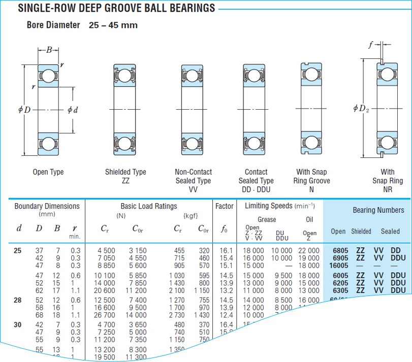 Figure 1: NSK E1102k 2012. B10
While pinning down the origins of the original limiting speed is vague, it is loosely based on a metric called DmN, a simple calculation of bearing pitch diameter ((inner diameter + outer diameter) / 2)) x rpm. This value is completely mechanical and mostly concerns the integrity of the cage, though as we will discuss, the cage is influenced by everything else. The catalog limiting speeds are based on a DmN of 500,000 for sealed bearings and between 600,000–750,000 for open bearings. For example, the top line in Figure 1: [(25+37)/2] x 18,000 = 558,000 for grease and 682,000 for oil.
The catalog is considered a safe, continuous operating speed. Somewhere between 700,000–1,000,000 DmN is considered moderate speed, which is still probably OK, but we must start dialing in clearances, making sure we don’t have large misalignments, our component tolerances are reasonably good, and we have a good supply of lubrication. When we go over one million, this is considered the high-speed region. Again, an off-the-shelf bearing may be fine in the low one-millions, but now our shaft, housing and absolute position tolerances should be very good (in the IT5/6 region which we will discuss another time) we also need to start thinking about cage strength, cage materials, fillers – glass and carbon fiber, and the dynamic mechanisms that we are going to discuss below.
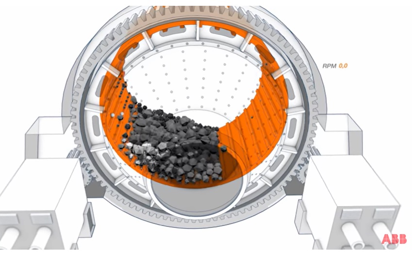
Let’s talk about forces acting on the cage. If you are wondering where these cage forces are coming from, you are not alone. If the bearing is perfectly aligned and the balls are turning with the rings, there should not be a lot of external forces, right? In many cases, the forces are negligible and why you find very thin plastic cages in many consumer-type products. When we get into higher speeds (beyond the catalog rating), the small forces can develop into forces large enough to compromise the cage integrity.
Outside of the obvious centrifugal force, there is a push-pull mechanism on a cage that is developed from the internal clearance of the bearing. If the bearing has zero clearance, as with a set of preloaded angular contact bearings, then the ball would be in perfect rolling contact 360 degrees around the raceway and there would be no tendency for the balls to slow down or speed up around the raceway. However, when we are dealing with a single-row deep groove ball bearing, we have an internal radial clearance to deal with. While this clearance is small, at high speeds it becomes a factor.
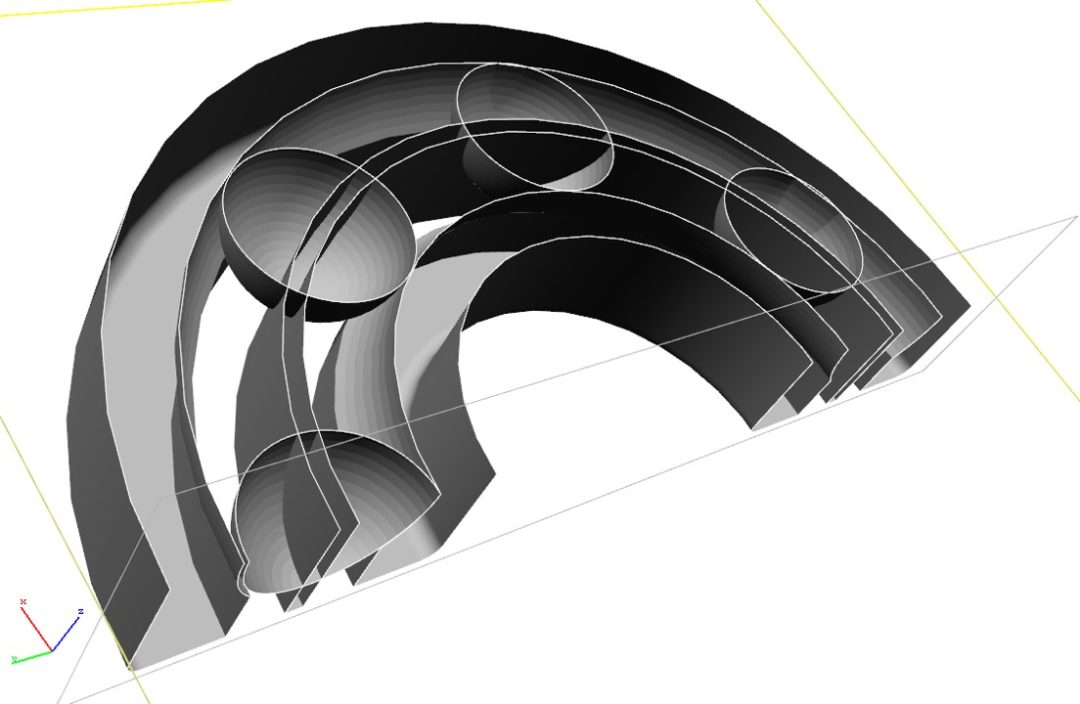
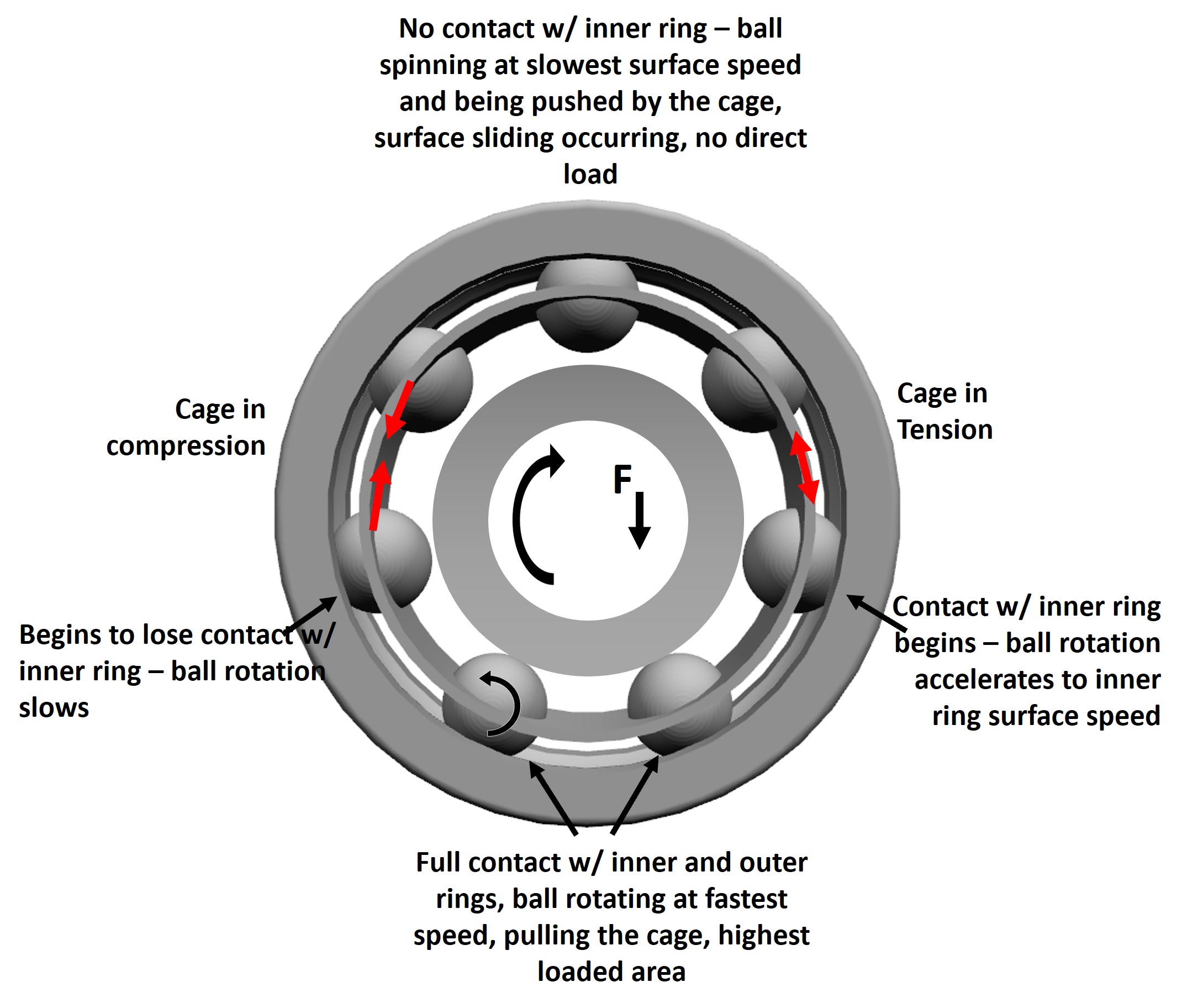 Figure 2: Different travel areas in and out of the load zone.
Figure 2 highlights the different areas of the bearing as it travels in and out of the load zone. At moderate to high speeds, the balls will stay in contact with the outer ring as they exit the loaded zone due to centrifugal force. From the point of losing contact, the only driving mechanisms for the balls are inertia and the cage. As the ball traverses the top of the bearing, some sliding is likely occurring as inertia is lost and the cage is pushing the balls. As the ball begins to reenter the load zone, they begin to accelerate to the inner ring speed again. During this brief acceleration area, the ball begins to pull on the cage. This dynamic is the elusive push-pull mechanism that you may have heard about. Perspective is important here. We might be running with 20 microns of clearance during operation, so these effects are small and happen in microseconds, but can easily occur over a billion times during the life of the bearing. You can see here that the amount of internal clearance will have an impact on how long the bearing is in and out of the load zone and the relative rotational speeds of the balls. You can begin to quantify these values with relatively simple math (though a lot of it) and we may tackle that in a future post.
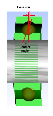
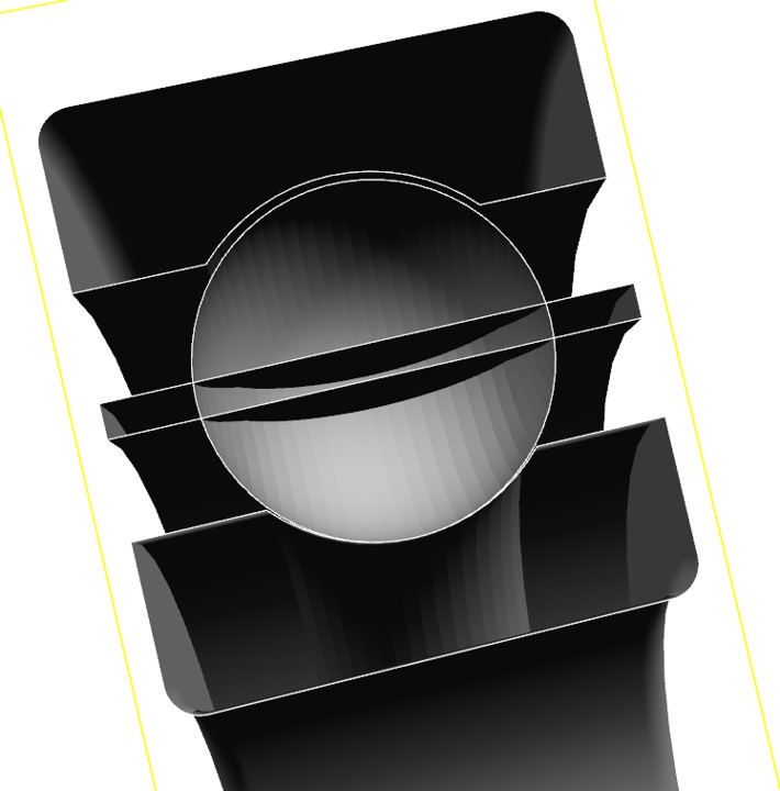
If the bearing is supporting a gear set, we likely have an axial load to deal with as well. This imparts yet another dynamic which we call excursion. After understanding the dynamics of clearance, this is an intuitive secondary mechanism that we need to understand—even if only understanding that axial loads put further stress on the cage. For a ball bearing under axial load, there is an offset between the inner and outer rings. This, in turn, forces the ball to run off-center. We refer to the angle that the ball is running on relative to the center of the raceway, the contact angle. Unlike angular contact bearings, this contact angle is not fixed and fluctuates with load. Just as with radial clearance, when the balls are in the load zone, they are locked into this contact angle by both rings. As the ball leaves the load zone and loses contact with the inner ring, the ball will drift back towards the center of the raceway due to centrifugal forces. This creates somewhat of an axial “wobble” as the ball goes in and out of the load zone and the magnitude is referred to as excursion.
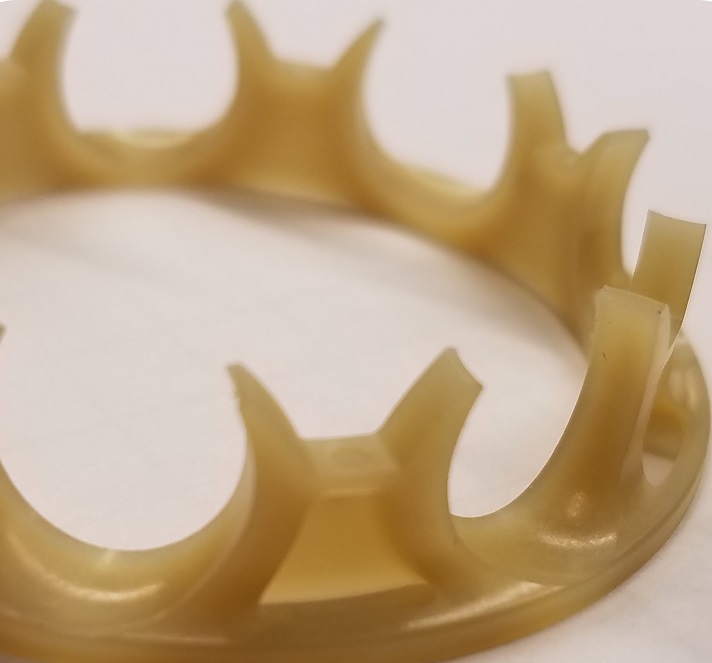
As you may know, axial clearance can be 10 times or more than the radial clearance just due to the geometry of the bearing. This means that a hard axial load can be much harder on the cage than a pure radially loaded bearing. In addition to the push-pull mechanism, the ball now radially pushes on the bearing pocket. One potential countermeasure for this is to loosen up the cage pockets a little or adjust the geometry to distribute the loads around the pockets more evenly.
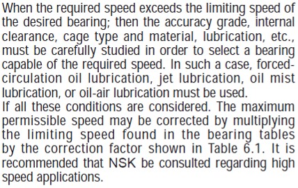
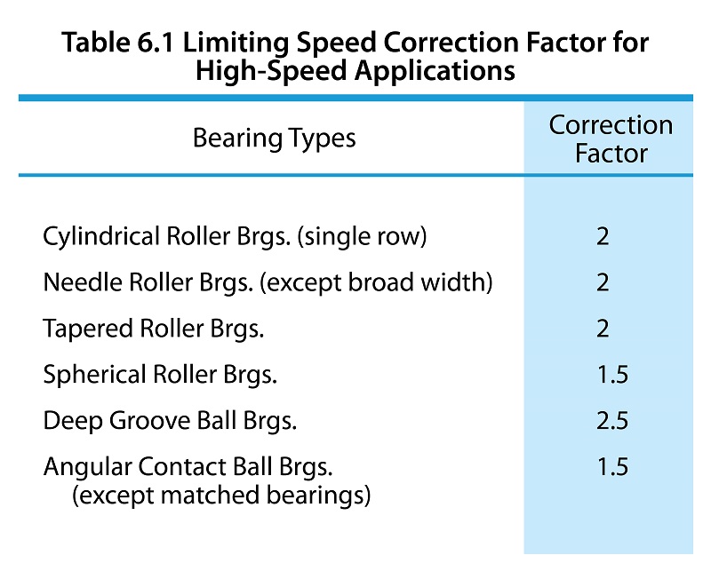
As a parting note to limiting speeds, I found this gem in a hard-to-find corner of an NSK catalog. This corrections factor suggests that if we optimize all our parameters, we can multiply our limiting speed by 2.5 for ball bearings, as we calculated earlier, which is around 1.2–1.3 million DmN—a fairly reasonable estimate. We will see how this compares to our thermal limiting speeds next time.