Aluminum Housing Series: Cup Distortion after Installation
The next step in our aluminum housing series is to determine where the cup interference is going. If we press a cup with 100µm interference into a solid steel block, most of that interference is going to compress the cup. If we press the cup into a block of jello, the cup isn’t going to compress at all. This is important to understand because the amount of cup compression plays a large role in the amount of preload you will lose with increasing temperatures.
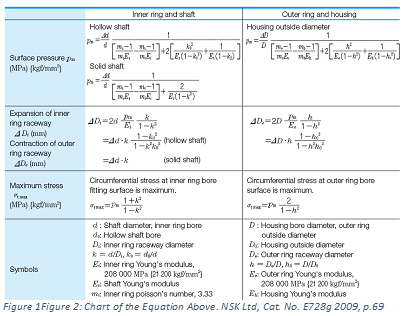
You can find several variations of a bearing hoop stress/strain formula. I like the NSK version from their Technical Report; everything is in one table with the variables defined for an easy one-page reference. This table contains surface pressure, maximum stress and actual ring contraction. This is a cumbersome formula, but well worth your time to set up in a spreadsheet in lieu of running a CAE analysis or guessing. Plan on a ½ day in a quiet spot to get this set up with an example bearing. My advice is to break this up into steps in a spreadsheet. My spreadsheet has 29 cells just for the formula and another 6 for bearing dimensions.

All bearings are a little different, but for an easy example, a 100mm cup with a 100µm interference with a 20mm thick wall will have ~ 20µm of compression with the remaining 80µm expanding the housing. For this example, you have a 1:5 ratio of cup compression vs. housing expansion. If you set your target to be line to line fit at 120C (from 25C), at the halfway point, 47.5C, your cup should have expanded by 10 microns with the remaining press fit of 50µm.
Last week we covered how to target your press fit. This week we talked about the methods to find how much of that press fit goes into the cup vs. the housing. Next week, we will discuss exactly how to convert the radial bore expansion into axial preload loss. That won’t be your only source of preload loss, don’t jump the gun just yet.
If you don’t have NSK’s Technical Report, download it here for free: http://www.jp.nsk.com/app01/en/ctrg/index.cgi?rm=pdfView&pno=e728g


