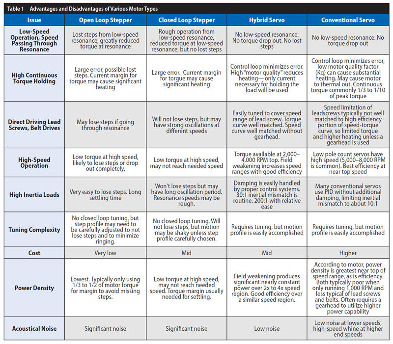
The open-loop stepper has a second-order system from the rotor inertia interacting with the effective rotary spring of the rotor magnet interacting with the stator magnetic field, which gives rise to low-speed resonance issues. The hybrid servo system commutates the stator field to keep the rotor-stator angle nearly constant, which essentially eliminates torque variation with angle. Without the spring, the rotary pendulum does not exist, and the low-speed resonance is eliminated. The motor can be used over the full range of speeds without torque dropouts normally seen with step motors.
The servo system tuning adds damping to the system. This damping allows for very rapid motions with very rapid settling and minimal overshoot. As only the current actually needed to produce torque is applied to the motor, motor heating is minimized, and efficiency is significantly improved. With full four-quadrant control of the current through the windings, tight control is maintained both when accelerating and decelerating the load. Integral control reduces the error, even in the presence of an offset force or friction.
Servo control of these motors produces a controlled-to-limit torque, which can be useful in applications such as tightening caps. Servo systems also allow the designer to add a secondary feedback device to allow the load position to be directly measured. Such a dual-loop system helps compensate for backlash and other distortions in the drive path, including leadscrew inaccuracies and pulley eccentricities.
A servo system may be made very rigid when stopped, while the current to the motor may be minimized to that actually necessary to counteract the load encountered. The positioning error can thus be significantly less than when these same motors are operated as step motors, while simultaneously reducing the motor heating. Operating these high torque density hybrid motors as servos also reduces the required torque margins, effectively allowing 2x to 3x more power out of the same-sized motors. Damping allows significant load inertia mismatch levels while still having stable and smooth operation.
Hybrid Servo versus Traditional Servo
The pole count of a motor times the number of turns in the winding times the flux density in the gap sets the torque constant for a motor. Traditional servo motors have low pole counts—typically one to 16 pole pairs, as each pole normally requires its own magnets, and the related stator slots are normally individually wound. Due to the lower pole count, traditional servo motors typically have a lower back-EMF and the resulting lower torque constant. Traditional servo motors typically also have significant end windings, which raises the winding resistance without adding to the motor torque. While the low back-EMF allows these motors to run at high speeds, the low torque constant also limits the continuous torque of the motor due to I2*R heating of the stator coils. Efficiency generally peaks near the upper speed limits of the motor, resulting in low efficiency at low speeds.
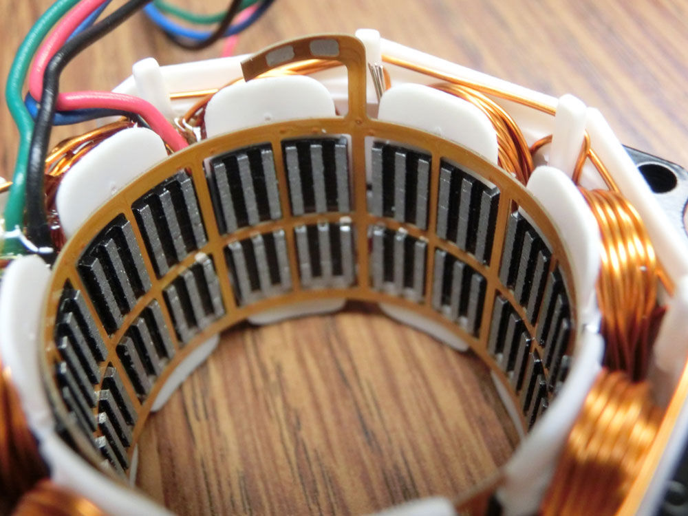
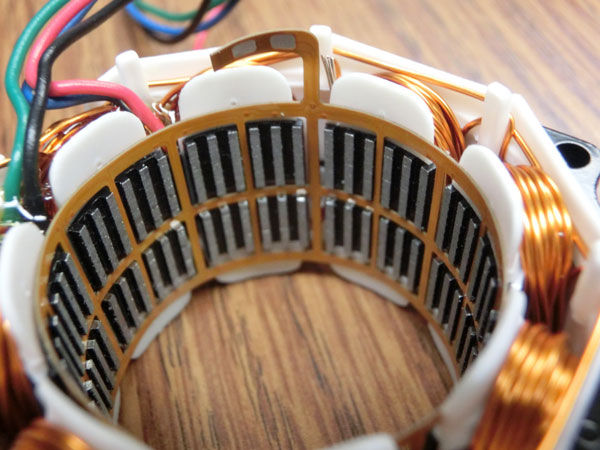 The Mosolver from Quicksilver Controls is an exampole of a full hybrid servo motor.
Hybrid servo motors have a much higher pole count—typically 50 (1.8 degree) or 100 pairs (0.9 degree). The design of the hybrid servo allows rotor magnets to be shared with many poles, enabling the high pole count while still having a simple design. The stator windings have a small end winding factor, so most of the copper is torque producing. The resulting structure results in a remarkably high motor quality factor (torque per square-root of power), allowing for high continuous torque. The trade-off is a lower top speed capability. This low speed limitation is often offset by not needing gearheads or in other cases as many stages of speed reduction for a given application.
What is Servo?
Original use of the word servo (from Latin for slave or keeper) was related to water clocks (aka clepsydras) of ancient times, which kept the flow of water constant by keeping the height of the water nearly constant. These mechanisms sensed the water height in a reservoir and allowed more water in when it started to drop below a threshold. Think of the floats in a modern toilet. So, to answer the original question: To be properly be called a “servo,” the mechanism must vary its operation in response to a measurement so as to reduce the variation in the measured parameter. Thus “closed loop” does not always equate to “servo”!
You can read more about ancient water clocks at https://aljazaribook.com/en/2018/09/04/castle-clock_en/
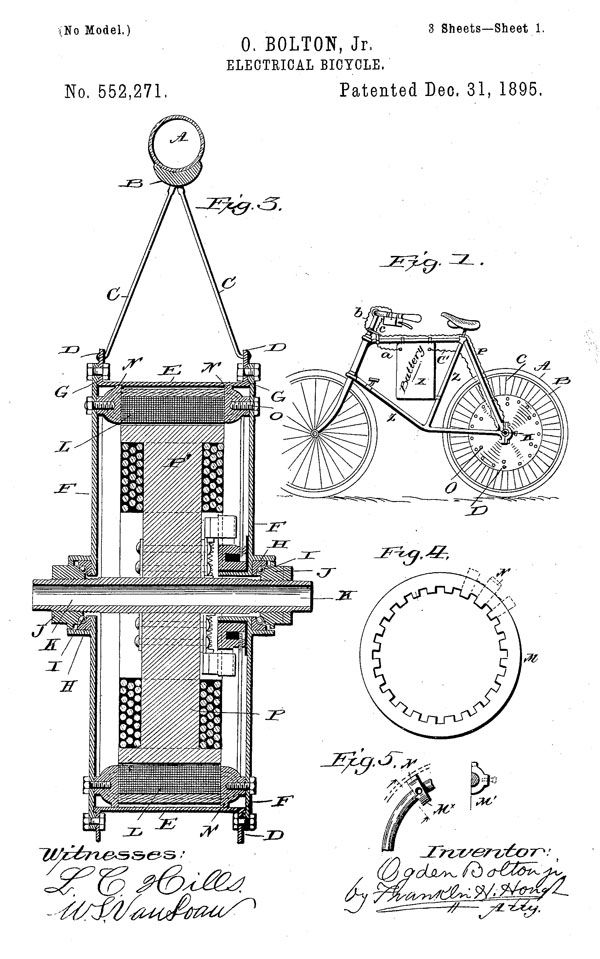 The first electric bicycles used a transverse flux motor, among the earliest forms of hybrid motors (U.S. Patent No. 552,271, from 1895).
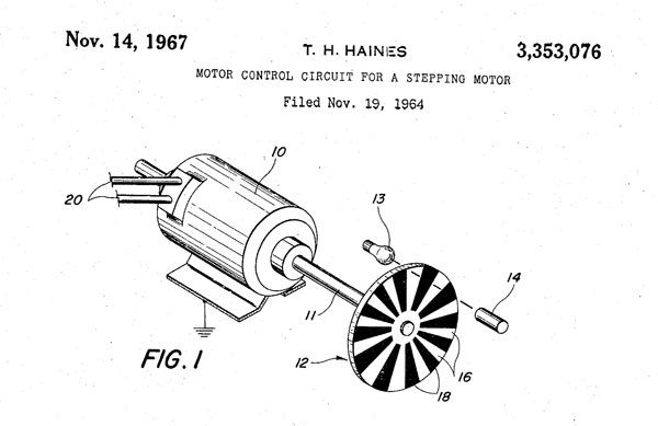 Among the earliest closed-loop steppers was this encoder-controlled motor (U.S. Patent No. 3,353,076, from 1967).




 Power Transmission Engineering is THE magazine of mechanical components. PTE is written for engineers and maintenance pros who specify, purchase and use gears, gear drives, bearings, motors, couplings, clutches, lubrication, seals and all other types of mechanical power transmission and motion control components.