Bearing Cap Pinch
Howdy Folks,
My apologies, I have been AWOL for a little while. Things can start to get a little sketchy around the PG as peak driving season ramps up.
I was recently approached for the 9000th time (at least) about fitting tapered bearing cups into bearing caps, which was my inspiration for this week’s post.
Bearing caps can be a fairly generic term, so let me clarify that I am specifically talking about bearing caps in a Salisbury style axle; which are the majority style of light duty truck axles used today.
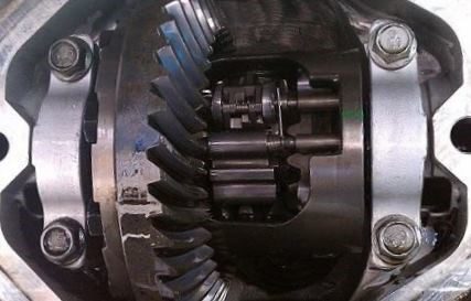
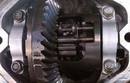
Generally speaking, you don’t want an interference fit on these bearing caps because they will distort and you tighten them down. If only it were that easy! For as long as bearing caps have been around, keeping them round has been the issue. Typically, the caps will be mated to carrier and machined as one assembled pieces. The prevailing theory was that if the cap bolts were tightened down enough so that the cap wouldn’t move during machining; the cap should be able to be removed and reassembled with the same tolerances it was machined to, right? Wrong.
It has been found the after the cap/carrier interface is machined, the measurements may be perfect until you loosen the bolts for the first time. The cap will often contract and give you an out of round cap. There are a couple of theories. I’m of the opinion that the machining operation imparts some compressive stress into the machined surface of the cap which aids in the contraction when the cap is removed.
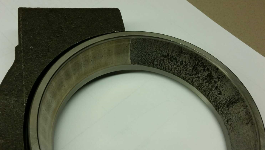
How much does the cap contract? It can be substantial. Substantial enough to fail a bearing at the split line location. Photo 1 below is a cap that was machined to perfection prior to removing the bolts and upon removal measured 120 µm out of round at the split line location; far beyond acceptable tolerances. To make matters worse, the out of round is very localized creating almost an edge at the split line. In testing, this cap wound up failing a bearing cup as the first failure in the axle taking about ½ of the life out of the axle.
For reasons I don’t yet completely understand, this problem seems to be more prevalent in cast iron housings. Aluminum housings don’t seem to exhibit this problem nearly as often as iron housings. It could be because the AL doesn’t get as hot during machining, but that is speculation on my part.
We’ll really get into this deeper in a full article, but for now, keep your cap fits light. I like to start off somewhere around a line to line fit. There are occasions, if you are having really bad contraction with heavy loads, you may have to back off farther than that.
Your comments on the bearing caps and crush etc in relationship with Salisbury style rear axles was interesting. I have been a machinist for over 40 years and heavily involved in prototype and unlimited top fuel and funny car racing for more than 25 years in a former life. I have machined many engine, transmission, and rear axle assemblies and then assembled them to perform in extreme conditions in the racing world. This has included many very large industrial engines etc. One of the things that I have noticed is that during line boring and align honing operations on both aluminum and cast iron blocks is the tendanacity for the main caps to pinch in at the parting lines regardless of the material but more pronounced at the parting lines. The cure for this is to loosen the cap to about 1/4th of the prescribed torque and stroke it a few times, then re-torque it to proper torque amounts and finish the align hone or align bore job. This will remove a very slight amount .0005″ or so in the area of approx 1/3rd to 1/4th of the caps hemisphere close to the parting line. After the line boring operation the caps will remain in tolerance when loosened and re-installed. This is particularly evident when the cap fits into a “register” in the block or housing. The tighter the fit the more it will have to be “relieved” to develop a correct diameter and roundness when reassembled. It does not hurt to remove and reassemble the caps 2-3 times before the final line bore, as this more clearly represents the “real” operating world the engine or rear axle housing will live in.
Rick,
Thank you so much for the reply. We need to talk about drag racing, but I’m going to try and stick to the subject (for now).
You answered several questions that I have had in mind. We had speculated that if somehow we could loosen the caps up during machining, that should work. We could never figure out a way to do it in production, so it was never more than an idea. I’m also glad you have seen this on aluminum. The lack of effect that I have personally seen may very well be just due to the different supplier we use for aluminum.
Thanks again!
Norm
The movement of bores after machine is a common phenomena and Rick is correct that loosening and then tightening the items during machining will allow for the final machining operation to maintain tolerances. The cause of the movement is most likely related to the residual stresses that exist in the part prior to machining. When you remove metal from one area of the part that is restrained, the balancing residual stresses are still locked in. Once you release the part, those residual stresses distort the part until the residual stresses are balanced again. This is why doing a preliminary machining, releasing the part to allow it to distort, then machining reduces the final distortion into acceptable levels and why the repeated steps of machining and releasing, machining and releasing allow for you to meet very tight tolerances. I don’t know the configuration of the cap that you are talking about, but it appears that it is not symmetrical. The residual stresses that are being relieved will affect the different areas differently based on cross sectional area, which may explain why the problem exists at the split line.
Hi DM,
Thanks for the feedback. Both you and Rick are doing exactly what I thought would be needed for hitting very tight tolerances with a cap. Now the trick is to figure out how to do this in a high production environment…
Best Regards,
Norm