We use cookies to provide you with a better experience. By continuing to browse the site you are agreeing to our use of cookies in accordance with our Privacy Policy.
  • TOPICS
    • Design
    • Manufacturing
    • Applications
    • Components
    • Industry
    • MRO
  • MAGAZINE
    • Current Issue
    • Departments
    • Archives
    • Subscribe
    • Advertise
  • NEWSLETTER
  • VIDEO
    • Power Transmission Engineering TV
    • Webinars
  • BLOGS
    • Revolutions
    • Editors Choice
    • Motor Matters with George Holling
    • Bearings with Norm
  • BUYER'S GUIDE
  • NEWS and EVENTS
    • Product News
    • Industry News
    • Events
  • Advertising
    • Brand Awareness
      • Print: Display Advertising
      • Print: Engineering Showcase
      • Online: Web Banners & Keyword Banners
      • Online: Sponsored Content (Native Advertising)
      • E-mail: Custom, White Papers & Webinars
      • Email: Sponsored Content (Native Advertising)
    • Response & Lead Generation
      • E-Mail: Sponsored Content (Native Advertising)
      • E-mail: Newsletters
      • E-mail: Custom, White Papers & Webinars
      • Online: Buyers Guide
      • Online: Sponsored Content (Native Advertising)
    • Print
      • Print: Display Advertising
      • Print: Engineering Showcase
      • Print: MPT Expo Showstoppers (October 2023)
      • Print: Buyers Guide
      • Print: Engineering sMart
      • Print: Specifications
      • MPT Expo Show Guide Advertising
    • Online
      • Online: Web Banners and Keyword Banners
      • Online: Buyers Guide
      • Online: Sponsored Content (Native Advertising)
      • Online: Specifications
    • E-Mail
      • E-mail: Newsletters
      • E-mail: Custom, White Papers & Webinars
      • E-mail: Sponsored Content (Native Advertising)
      • E-mail: Specifications
    • Special Promotions
      • Print: Engineering Showcase
      • Print: Showstoppers (MPT Expo)
      • Print: Buyers Guide
      • Print: Engineering sMart
      • MPT Expo Show Guide Advertising
  • Contact Us
  • AGMA
    • Membership
    • Events
    • Education
    • Emerging Technology
    • AGMA Media
      • Gear Technology
      • Gear Technology India
    • Standards
Subscribe
  • Sign In
  • Create Account
  • Sign Out
  • My Account
Home » High-Precision Brushless DC Rotary Motors Optimal for Pick-and-Place Robots

High-Precision Brushless DC Rotary Motors Optimal for Pick-and-Place Robots

pt0623_Page_48_Image_0001.jpg
June 5, 2023
Edward Neff

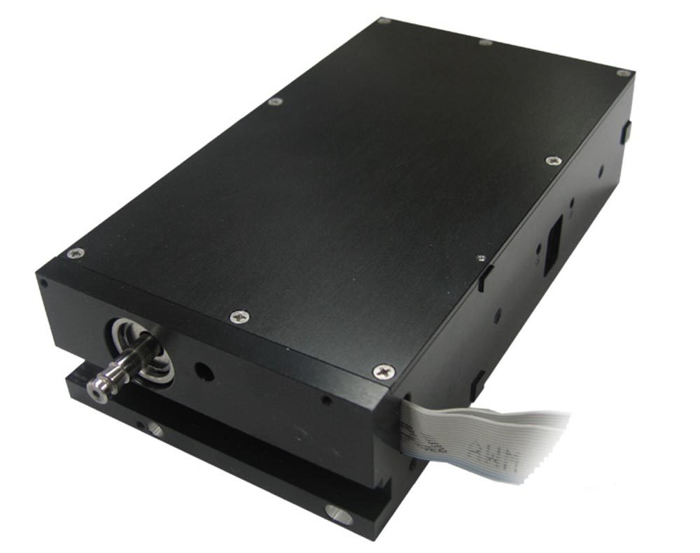
The SMAC LAR31 Linear Rotary Actuator has 17 micron true position tolerance for dowel holes, making it ideal for high-precision circuit board assembly.

In electronic automation precise movement is a basic requirement for successful assembly. Both linear and rotary motion demands a high level of precision needed in circuit board assembly, assembling camera lenses and speakers in smart phones and other electronic assembly applications.

The best linear motion solution uses linear motors. Small, precise brushless motors are most often used for rotation.

There have been several recent technical advances in the design and production of precision linear and rotary pick-and-place robots that meet the ever-tightening requirements of the consumer electronics and back-end electronic assembly industries.

The Requirements

The general trend for assembly is the need for more precision. This is the result of the continually shrinking size of electronics and even mechanical parts. As electronics get smaller, so does the margin for error in assembling them. In rotary motion, the accuracy of placement must increase.

Most electronic assembly today involves the inspection of parts by camera or laser before they are added to the smart phone, computer, or other device. No part is perfect; they all vary because the world really is non-Euclidian! Therefore, the placement position of each part must be slightly and variably adjusted before assembly. This also occurs in camera lens assembly, for example, where part-tolerance variation is large but the stack up tolerance is small.

pt0623_Page_49_Image_0003.jpg

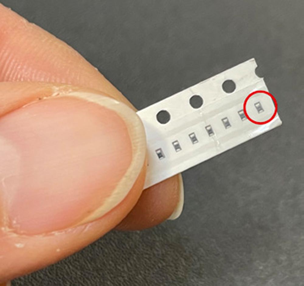
Assembling resistors and capacitors requires extreme precision due to their small size.

Rotary motor positioning requirements call for accuracy of ±0.1 degree or better. Rod runout must be less than 10 microns and the diameter of the motor must be less than 15 mm, and that is moving toward 8 mm.

These demand constraints put pressure on motor and encoder manufacturers to improve their design and manufacturing methods. To meet demands, manufacturers can do several things:

  1. Improve the electrical design of the motor. This can be accomplished in a couple of ways.
    1. Use printed coil technology rather than winding coils using wire and electromechanical winders. Motor wire for these types of small motors is very thin, which makes precision winding a challenge. A printed coil is basically a flexible printed circuit. The “wire” is replaced by printed circuits on a strip. “Printed” wire is like square wire used in high-end speakers. The wire width and height are not tied to set gauge sizes, which means higher torques can be achieved, especially because speed is not critical.
      This strip is then wound and formed into a resulting coil. The process is very precise as it is essentially the same as that used in circuit boards. The coil resistance is very repeatable and, since there is no wire fed from a spool or tensioning to worry about, is a factor of 10 tighter than conventionally wound coils. A significant side benefit is greatly reduced cogging effect compared with that seen in conventionally wound brushless motors. A further benefit is that there is no special tooling cost. Circuit board manufacturing is highly automated, so the setup cost is built into the price of the board. It is also faster to get started as the time from design release to production is a couple of weeks.pt0623_Page_49_Image_0002.jpg
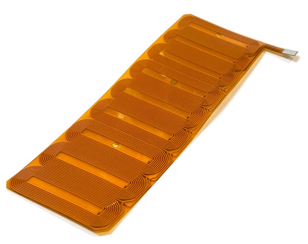
SMAC uses printed coil technology for its rotary motors. The coil is basically a flexible printed circuit which requires no additional cost for tooling.


    2. Use molded soft laminations, which are rapidly replacing stacks of stamped lamination rings. Again, the effect on cogging and the cost of production are drastically reduced.pt0623_Page_49_Image_0001.jpg
    3. Molded soft laminations eliminate stacked rings, reducing cogging and cost of production.


  2. Improve the accuracy of the encoder.
    1. Build the disc and hub directly onto the shaft of the motor. Many encoders are coupled to the motor shaft, which causes error and can add side-load to the shaft increasing its runout. If the hub-disc assembly is press-fitted onto the shaft, error is reduced.
    2. Use laser technology to make the disc. Lasers are rapidly replacing old mechanical manufacturing methods like mills and saws. Lasers that run on linear motors are extremely precise and can hold disc size/track variation to less than 5 microns, easily a factor of 10 times better than conventional methods. This eliminates the need to make mechanical placement adjustment, which includes precision cameras that can detect down to a micron.
  3. Reduce the rod runout.

pt0623_Page_50_Image_0001.jpg

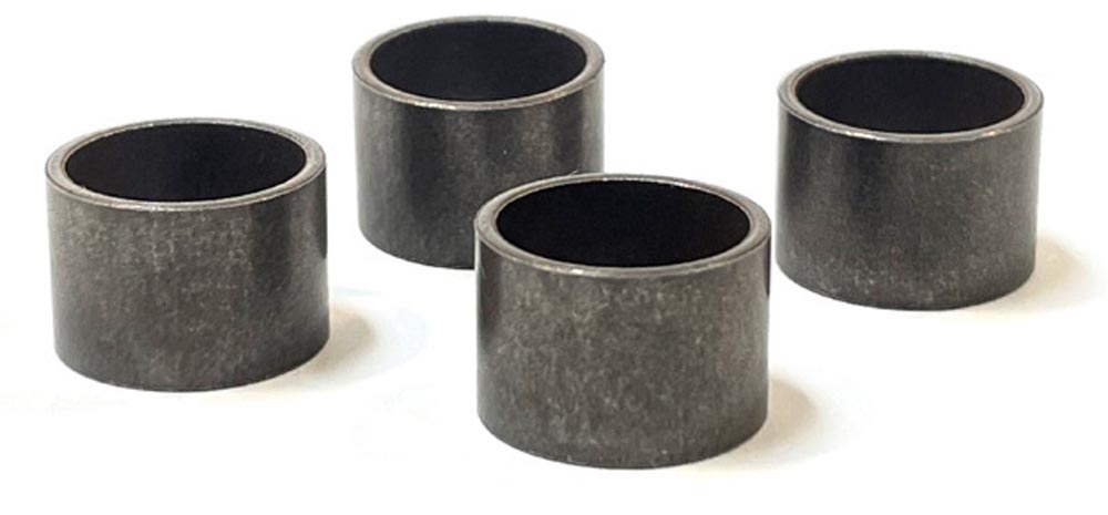
Stator housing holds both bearings in line, keeping lathe bore diameter and straightness variance to within 1 to 2 microns.

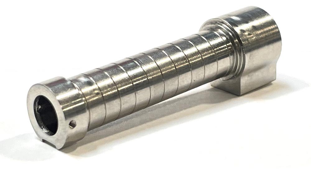
A ground shaft can normally meet a straightness requirement of less than 5 microns. Bearings have a positive effect on runout however, greatly reducing runout.

  1. Mount both the front and rear bearings in a stator bore that has a single diameter. The single bore lines up the bearings precisely with each other. It is possible on certain lathes to hold that bore to within 1 to 2 microns of diameter and straightness variance.
  2. Use a threaded bearing preload adjuster and wave spring to precisely set the preload. Until now, most designs use spacers and wave springs. There may be several thicknesses of spacers and wave springs stacked. An adjustable threaded spacer, combined with a single wave spring, is screwed into position while monitoring the effect on motor starting torque to reach a target close-loop preload.

pt0623_Page_50_Image_0002.jpg

Adjustable preload can be closed looped to set extremely precise load.

pt0623_pg_50_Image_0001.jpg

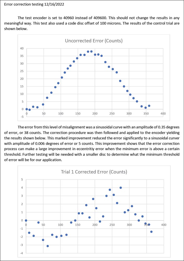
Accuracy testing shows error well under 0.1 degree.

The result is a rod runout of less than 10 microns, and often even less than 5 microns.

  1. Add vacuum pick-up / gripper operation capability.

Although the use of pneumatic devices is coming to an end in electronic assembly, there still are several limited application areas.

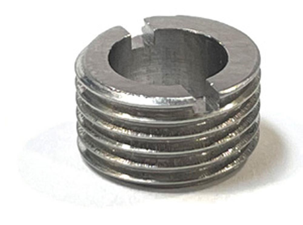
The first is a vacuum, the most common way to pick up small, fragile parts. The vacuum flow also picks up dust that is on and around the components to be picked up. A good design for the motor is to have a shaft with a hole that runs through the motor to direct dust outside the motor and into the vacuum device which has filtration.

Grippers are often used for larger components. Grippers tend still to be pneumatic, mainly due to the lower cost. The same through-hole shaft design, combined with correct sealing, means that pressurized air can move through the motor and into the gripper.

In conclusion the long-term trend in electronics is moving toward higher-density components in smaller and smaller package sizes. Pick-and-place robots now have nominal widths of 13 mm which move to 10 mm, and very soon 8 mm. Robot makers must keep up the development pace to meet the challenge. This means 8 mm motors with 10 millinewton-meters (mNm) of torque and encoders with 20,000 steps per revolution.

Invention combined with never-ending improvement is the key. Brushless motors are following this trend for rotary motion just like linear motors are for linear movement. And this technology is spreading into robotics, particularly in end-effector evolution. That’s where there really is a need for a helping hand. Practical robotic fingers and hands will soon be a reality.

smac-mca.com

Automation Motion Control Robotics Actuators Linear Motion Motors Technical Articles
KEYWORDS motors
  • Download This Article

  • Related Articles

    Improve Thermal Performance for Ironless Brush DC and Brushless DC Motors

    Kollmorgen Examines Five Brushless Servo Motor Components

    How to Select a DC Motor: Coreless and Iron Core Brushed DC Motors

Pt0623 page 51 image 0001
Edward Neff

More from this author
Free Power Transmission Engineering Subscriptions
Subscribe
Free Power Transmission Engineering Subscriptions
Subscribe
FEATURED VIDEO
  • Pcb camroller
    PBC Linear: Cam Roller Technology Overview
December 15, 2022
RECOMMENDED
  • A Closer Look at TPS

    September 5, 2023
    HERO-Packed-Exhibition-Aisle.jpg
  • A Guide to Gearmotors

    August 31, 2023
    Fig1.jpg
  • Pack Expo Las Vegas 2023 Highlights Automation and Material Handling Technology

    August 28, 2023
    Expo1.jpg
  • Power Up Your Participation

    September 8, 2023
    Detroit Skyline1.jpg
  • Five Crucial Steps to Minimize Wear and Tear of Motion Components

    September 5, 2023
    Limble1.jpg
  • Power Up Your Participation

    September 8, 2023
    Detroit Skyline1.jpg
  • Five Crucial Steps to Minimize Wear and Tear of Motion Components

    September 5, 2023
    Limble1.jpg
  • A Closer Look at TPS

    September 5, 2023
    HERO-Packed-Exhibition-Aisle.jpg
  • Subscribe
  • Advertise
  • Contribute
  • Gear Technology
Powered byAGMA
Copyright © 2023 Power Transmission Engineering
  • Privacy Policy
  • Contact